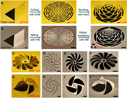
Fig. 1. Macro-kirigami and nano-kirigami.

(A) Camera images of the paper kirigami process of an expandable dome (corresponding to a traditional Chinese kirigami named “pulling flower”). (B) SEM images of an 80-nm-thick gold film, a 2D concentric arc pattern and a 3D microdome. The high-dose FIB milling corresponds to the “cutting” process, and the global low-dose FIB irradiation of the sample area (enclosed by the dashed ellipse) corresponds to the “buckling” process in nano-kirigami. The buckling direction is downward along the FIB incident direction (fig. S1G). A 3D feature size of 50 nm is shown in the inset. (C to F) A 12-blade propeller and (G to J) a four-arm pinwheel formed in a macroscopic paper and a gold nanofilm, respectively. Top-view SEM images of the milled 2D patterns before (D and H) and after (E and I) global FIB irradiation from the top, respectively. (F) and (J) are the side views of (E) and (I), respectively, which are in good correspondence to the macro-kirigami in (C) and (G). The dashed lines in (H) and (I) indicate a connection between two corners of the central structure, revealing a rotation angle of ~41° by nano-kirigami. The in situ fabrication can be programmed into one step (movie S1). Scale bars in SEM images, 1 μm.
