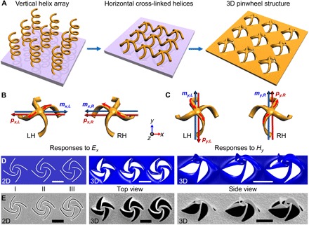
Fig. 3. Functional designs for optical chirality.

(A) Schematic of vertical helix array, horizontal cross-linked helices, and a 3D pinwheel array [the 3D pinwheel can also be treated as two cross-linked and twisted ohm-shaped circuits (28) standing onto a metallic hole array]. (B and C) Illustration of the responses to the (B) electric field (Ex) and (C) magnetic field (Hy) of incident light for the LH and RH twisted pinwheels, respectively. The direction of induced electric moments pi,j (i = x or y, j = L or R) and magnetic moments mi,j at the center parts is noted by the arrows for LH (j = L) and RH (j = R) pinwheels, respectively (generalized from the simulated results in fig. S7). (D) Numerical designs of three 2D spiral patterns (types I, II, and III), the top view, and side view of the numerically predicted 3D structures, respectively, under the same residual stress distribution. (E) SEM images of the fabricated 2D patterns and corresponding 3D pinwheels after global ion irradiation with the same doses, agreeing excellently with the numerical predictions. Scale bars, 1 μm.
