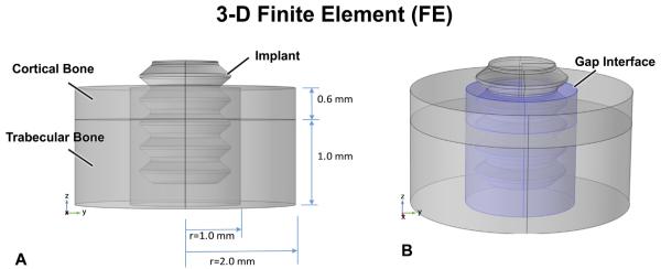
Fig. 2.
In the FE model, the bone site is idealized as being cylindrical with a 0.6 mm-thick cortical bone having trabecular bone underneath (A). However, the “gap” interface (B, blue shading in right figure) – produced by the 2 mm diameter drill – surrounds the 1.7 mm-diameter implant; the mechanical properties of this gap region can be altered to explore the influence of healing. The top surface of the implant is loaded as per the protocols described. The sides and base of the FE model are constrained.

