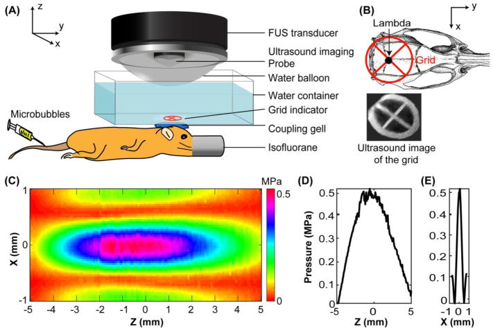
Figure 1.
(A) Illustration of the FUS treatment setup. (B) Illustration of FUS targeting of the pons with the assistance of a grid. The grid was placed on top of the mouse head with the center of the grid aligned visually with the lambda. B-mode images of the grid were obtained and reconstructed to 3D for the identification of the grid crossing point. The left pons was targeted based on its stereotactic location in reference to the lambda. (C) 2D pressure map of the FUS beam at the axial focal plane. (D) Axial and (E) lateral pressure profiles across the focus. The directions of the axes (X, Y, and Z) are added in (A) and (B) to help understand the positioning of C, D, and E with respect to the mouse.

