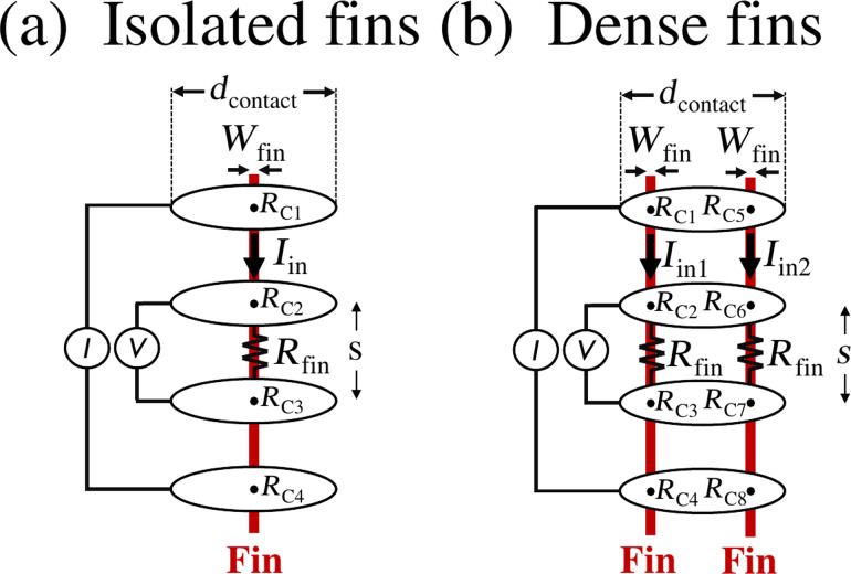
Figure 1.
Top-view schematic of the four μ4pp electrodes landed on (a) a single fin and (b) two fins. The electrode contact size and the contact resistance for each electrode–fin contact are, respectively, indicated by dcontact and RCj (j = 1, 2,…, 8). Note that all contact resistances are initially considered to be highly resistive because the native oxides present on both the fins and electrodes prevent current flow into the fin. Rfin is defined as the resistance of the fin between the two inner contacts, i.e., Rfin = Rs × s/Wfin, where s is the distance between the two inner contacts and Wfin is the fin width.

