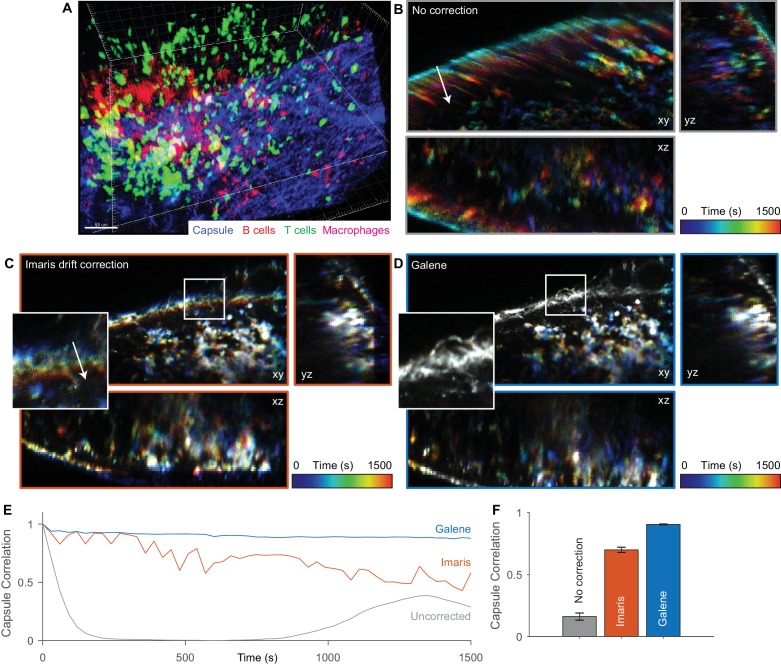
Figure 7. Motion correction of multispectral 3D imaging of labelled immune cells in a murine lymph node.
tdTomato labelled B cells (red), Kaede labelled OT2 T cells (green) and subcapsular sinus macrophages labelled with Alexa 680 (magenta) imaged in a 150 μm z-stack through the inguinal lymph node (SHG signal from fibrillar capsule, blue) over 30 min. (A) One time point rendered volumetrically. (B–D) Temporally colour-coded (blue, early time points; red, late time points) orthogonal projections of time series (with spectral channels merged) with (B) no correction, (C) Imaris drift correction and (D) motion correction with Galene. Inset, expanded view of region highlighted in white. (E) Correlation between the stationary collagen and macrophage signal for each volume in the sequence and the reference volume for each package. (F) Average correlation for each correction package. Results show mean ± SEM, calculated per time point.


