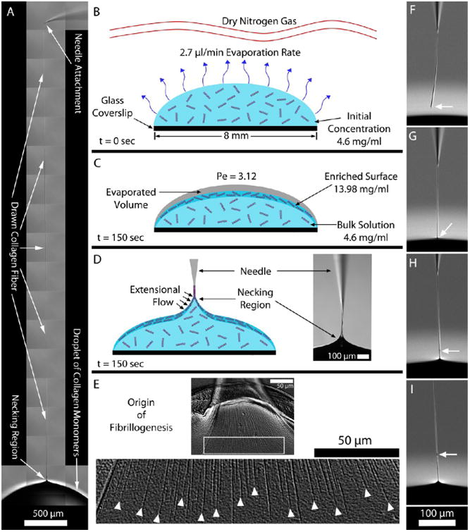
Figure 1.

(A) Fiber drawn from a droplet of collagen solution demonstrates the high aspect ratio fibers that can be created. (B–D) Cross-sectional schematics of the collagen droplet and surrounding environment at different time points. (B) Dry nitrogen gas was passed above the droplet to facilitate evaporation from the droplet surface. (C) After 150 s, an enriched monomeric surface was produced as a result of the water molecules exiting the droplet faster than the collagen molecules could diffuse into the bulk (calculated Peclet number (Pe) was 3.12). At this point, a collagen fiber could be reliably drawn from the droplet. (D) Glass microneedle was used to pierce the droplet surface and then drawn back outward. As the meniscus of the droplet drained from the microneedle, a collagen fiber persisted. (E) Fiber formation process was triggered by the applied extensional strain caused by pulling the microneedle away from the droplet. The top image shows the aligned fibrils being drawn into the fiber. The image below shows a magnification of the white box. Here, it is clearly observed that the fibrils begin in the necking region. The white arrowheads denote where the extensional strain rate likely reached the critical value required to initiate fibrillogenesis. (F–I) Image sequence demonstrates the repair of a collagen fiber (full video in Movie S4). (F) End of the collagen fiber segment is identified by the white arrow. (G–I) Fiber segment end was placed into the droplet and drawn out, initiating a repair site (white arrow) and the continuation of new fiber formation.
