Figure 8.

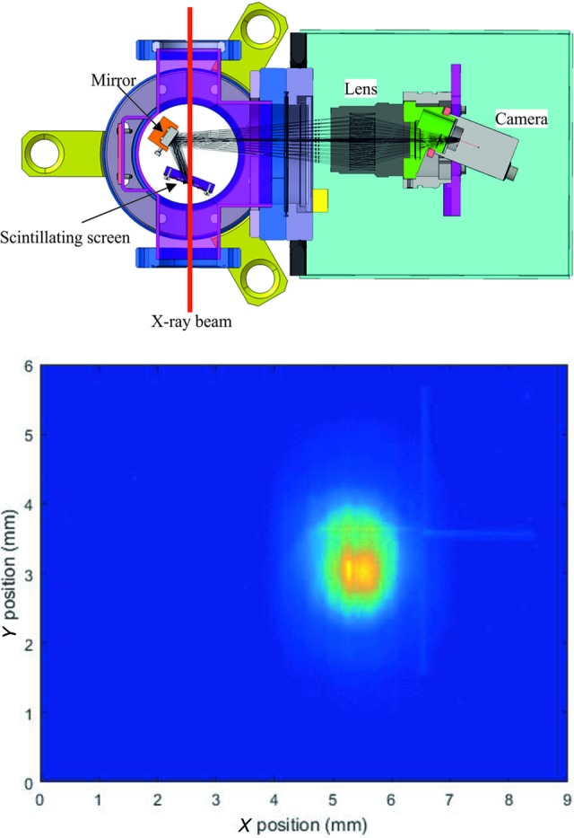
Schematic top-down view of the PPRM design with the optical paths drawn in (top) and an image taken during commissioning of one of the attenuators (bottom).

Schematic top-down view of the PPRM design with the optical paths drawn in (top) and an image taken during commissioning of one of the attenuators (bottom).