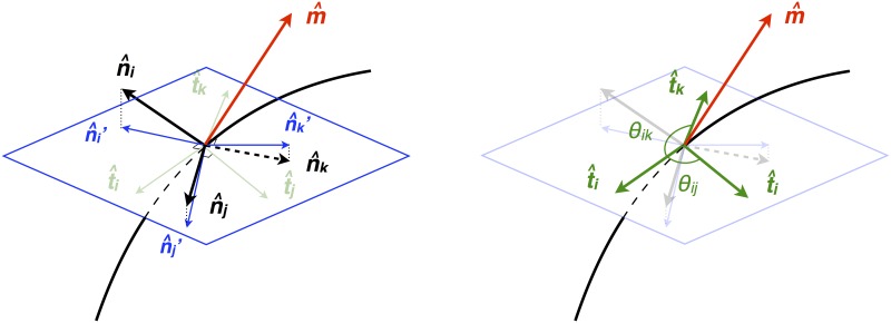
Fig 4. Schematic for tangent and angle computation.
The black curved line represents the junction and the black arrows tagged by , , and represent the normal vector of each membrane face. The red vector is an approximation to the junction’s tangent vector. The blue plane represents the perpendicular plane to the red vector . The blue vectors are the projected normals, which lie in the plane normal to , and thus are coplanar. On the right, we demonstrate that the angle of intersections can be calculated from the tangent vectors , , and from each membrane normal to the junction.

