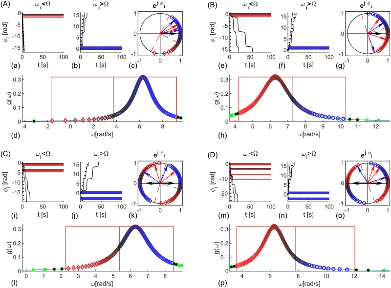
Fig 7. Delay-imposed populations of coupled heterogeneous phase oscillators.
(A, B) In- and (C, D) anti- phase synchronized clusters, at frequency (A, C) Ω < μ and (B, D) Ω > μ. (a, b, e, f, i, j, m, n) Phases ϕi(t) of the synchronized (red and blue) and two unsynchronized oscillators (black) closest to the limits of synchronization, and ±(Ω − μ)t (dashed). (c, g, k, o) Geometric representation of ϕi of the synchronized oscillators (different shades of red diamonds for ωi < Ω and blue circles for ωi > Ω). Limits and are dashed red, the arrows are for the complex order parameter (black) of each subpopulation (they overlap for in-phase), angles Ωτ1,2 (blue), and and ΩΔτ (red). (d, h, l, p) PDF of the natural frequencies, frequency of synchronization Ω (black vertical line), and limits of synchronization (red). Entrained oscillators are blue and red, the first two un-synchronized on both sides are black, and the rest are green. The colors of each oscillator are consistent across the plots. Parameters: N = 300, K = 7, Lorentzian natural frequencies with μ = 1Hz and γ = 1. (A) τ = [0.05, 0.2]s, (B) τ = [0.7, 0.95]s, (C) τ = [0.22, 0.47]s, and (D) τ = [0.04, 0.27]s.

