Revised Figure 1.
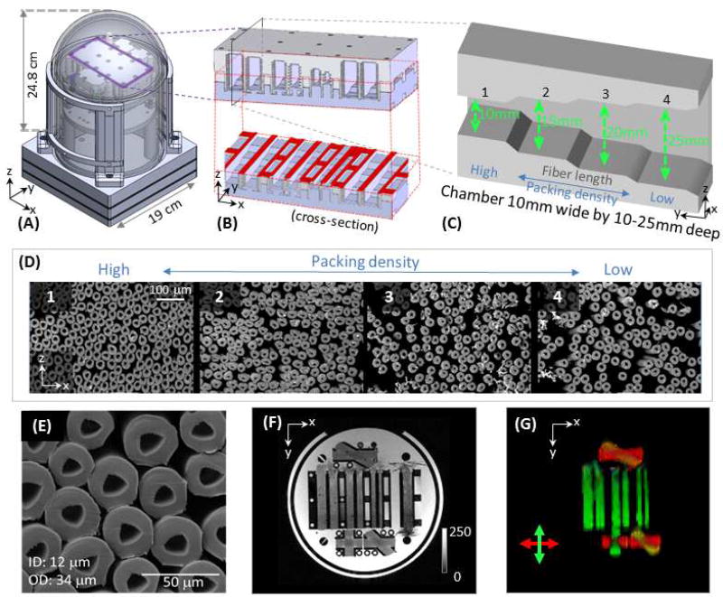
Phantom composition. (A) Diagram of the phantom, which measures 24.8 cm from top of the dome to top of the base and 19 cm in diameter. The taxon holder inside the phantom was 3D-printed, and the central piece was outlined in purple with a three-dimensional schematic inset shown in (B). An “axial” cross-section (outlined in red) is shown to reveal the internal structure of the individual chambers. Each chamber has 4 “steps” along the length of the chamber to achieve variable packing densities. A “sagittal” cross section (see plane labeled in black in B) was shown in (C), where taxon fibers ran along the length of the chamber, so that a wider depth in the chamber yielded a lower packing density. (D) Scanning electron micrographs (SEM, obtained with 220× magnification) of the taxon fiber bundles with different packing densities (numbers correspond to the sections of the chamber numbered in C). (E) A zoomed-in view of the SEM showing the size of the taxons (ID 11.8 ± 1.2 µm, OD 33.5±2.3 µm). (F) An overview of the diffusion phantom shown with a GRE image. (G) A colored FA map demonstrating principal diffusion directions. An x-y-z coordinate system is labeled on subfigures to assist in orienting the reader, where x, y, and z correspond to the left, posterior and superior directions, respectively, in the magnet.

