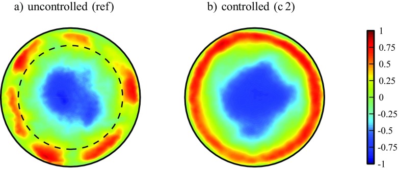
Fig. 16.
(Color online) Contours of the (instantaneous) streamwise velocity w in the cross-section of the pipe. The laminar flow field has been subtracted to emphasize near wall streaks (color bar expressed in units of the bulk velocity). a is the unmodified turbulent reference flow and b depicts case c 2 with an injection flow rate as indicated in Fig. 10b by a  (Re = 4000, z = 2.5). y+ ≈ 60 is indicated by the dashed circle

