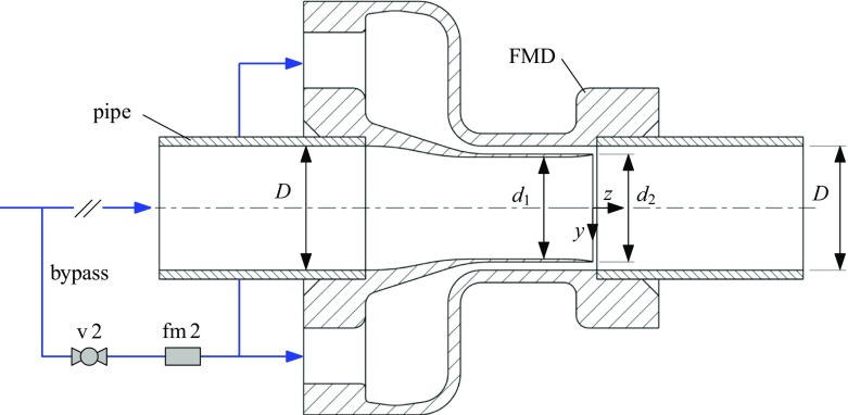
Fig. 3.
Sketch of the control device acting as injection nozzle through an annular gap (1 mm-FMD and 2 mm-FMD). Fluid is taken from the main pipe via a bypass and then re-injected through a concentric gap close to the wall. The device is mounted within two pipe segments. The bypass is equipped with a valve (v 2) and a flowmeter (fm 2). The flow direction is from left to right. Drawing not to scale

