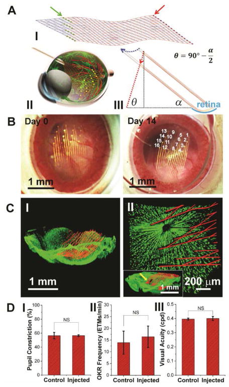
Fig. 1. Non-coaxial intravitreal injection and conformal coating of mesh electronics on the mouse retina.
(A) I, Schematic showing the layout of mesh electronics comprising 16 recording electrodes (green dots indicated by a green arrow) and I/O pads (red dots indicated by a red arrow). II, Schematic showing non-coaxial intravitreal injection of mesh electronics onto the RGC layer. Multiplexed recording electrodes are shown as yellow dots. III, Schematic of non-coaxial injection that allows controlled positioning of mesh electronics on the concave retina surface (cyan arc). The blue and red dotted arrows indicate the motion of the needle and desired trajectory of the top end of the mesh, respectively (see fig. S1 for details) (22). (B) In vivo through-lens images of the same mouse eye fundus on Day 0 and Day 14 post-injection of mesh electronics, with electrode indexing in the Day 14 image (22). (C) Ex vivo imaging of the interface between injected mesh electronics (red, mesh polymer elements) and the retina (green dots, RGCs) on Day 0 (I) and 7 (II) post-injection. The inset of II shows the region indicated by a yellow arrow where the high-resolution image was taken (22). (D) Comparison of pupillary reflex (n = 3), OKR (n = 5) and visual acuity (n = 3) between control and injected mouse eyes. The error bars indicate ±1 standard deviation (s.d.). NS, not significant (P > 0.05). One-way ANOVA test is used for statistical analyses.

