
Figure 5.
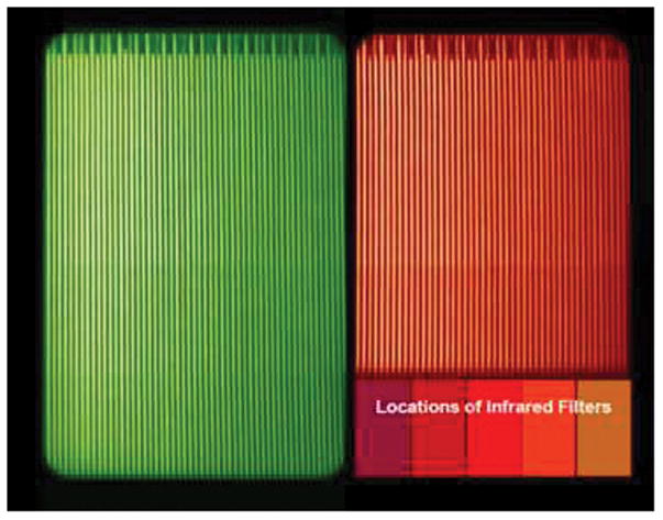
CCD image from one MIGHTI sensor taken during calibration showing the separation of the green and red/IR images. The fringes evident in the red and green wind channels are from Ne and Kr calibration lamps, respectively. The Earth’s limb, which is imaged on the CCD is oriented such that high altitudes are at the top of the image. The marks at the top of each image are burned into one of the interferometer gratings and are used to correct for any mechanical drift between the interferometer and the CCD. In normal operations the vertical direction will be binned a factor of 8 more than this image to obtain an altitude sampling of approximately 2.5 km.