Fig. 4.
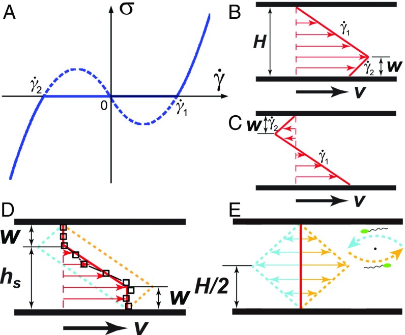
Duality of shear configurations. (A) A schematic showing the constitutive relation of active fluids from hydrodynamic theories (21, 22). The nonmonotonic trend predicts shear-banding flows with two shear bands of opposite shear rates, and . The corresponding shear profile are shown in B and C. Red arrows indicate shear velocities at different heights. Gap thickness, , and the width of the shear band with , are indicated. (D) Symmetric shear profile (thick red line) resulting from the average of the two shear configurations in B and C (yellow and blue dashed lines). Symbols are the experimental shear profile at and = 0.26 s−1. The stop height, , is indicated. (E) The duality of shear profiles at zero applied shear rate . The mean flow is zero (thick red line), whereas the two shear-banding configurations (yellow and blue dashed lines) are symmetric with respect to the mean flow. (E, Inset) At given , the two configurations moving along and against the shear flow complete a swarming vortex in the plane.

