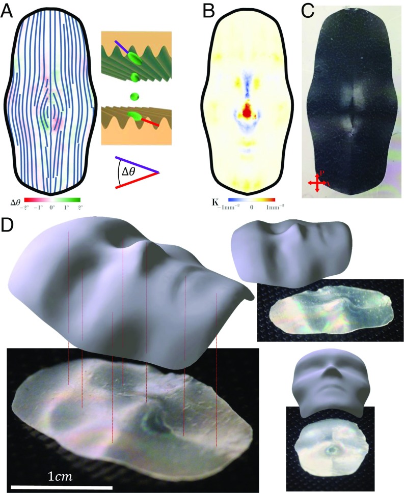
Fig. 5.
Designing a face using both metric tensor and curvature tensor. (A) Two slightly different director fields are imposed on the top and bottom surfaces of the LCE sheet. Shown streamlines indicate the director field at the midplane, while color indicates the angle difference between the top and bottom (illustrated by Inset sketch). (B) Gaussian curvature of the target surface. The correlation between regions with strong negative Gaussian curvature and regions with strong stems from the saddle-like form of the induced curvature tensor. (C) Polarized optical microscopy is used to verify the resulting director field throughout the LCE sheet. (D) At the target temperature the LCE sheet takes the shape of a face.

