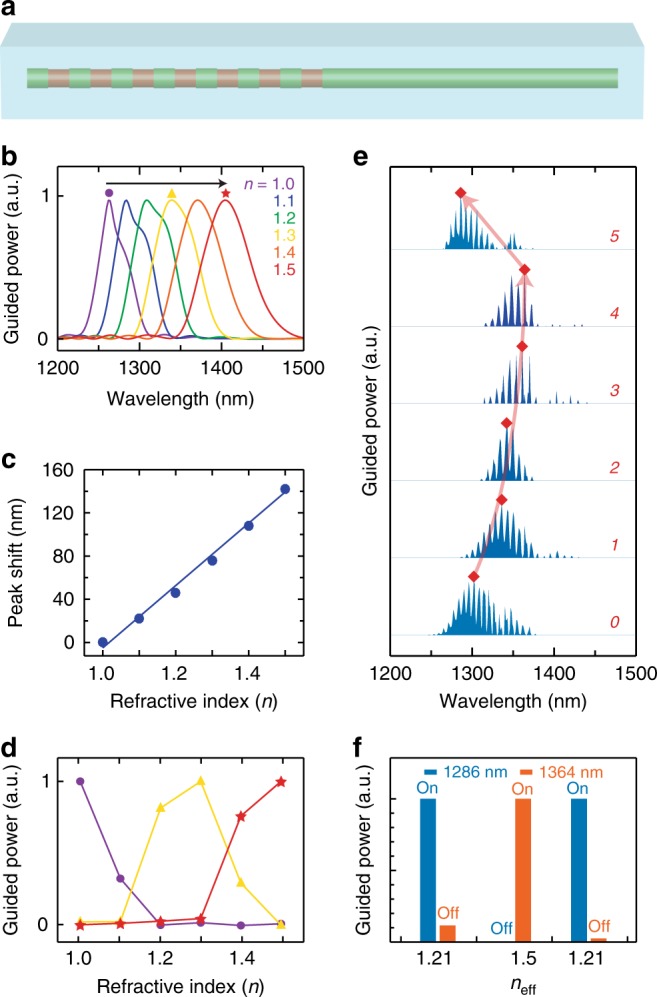
Fig. 5.

Optical switching in a GSL-WG. a Schematic of a GSL-WG in which the refractive index, n, of the surrounding medium (blue) changes from 1 to 1.5. b Simulated guided power spectra for a GSL-WG with d = 280 nm, e = 250 nm, and p = 800 nm for n varying from 1 (blue) to 1.5 (red) in steps of 0.1. c Plot of guided peak position shift versus refractive index n. d Normalized guided power versus refractive index at wavelengths of 1262 nm (purple circles), 1338 nm (yellow triangles), and 1404 nm (red stars). Spectral positions correspond to the marker symbols in b. e Experimental guided power spectra of a NW WG with a GSL of d = 280 nm and p = 820 nm measured without PMMA (0), after sequential additions of up to 4 PMMA layers (1–4), and after removal of PMMA (5). Red diamonds and lines denote the spectral position with maximal guided power for each spectrum. f Normalized guided power at wavelengths of 1286 and 1364 nm derived from spectra labeled 0, 4, and 5 in e, which correspond to estimated effective indices of 1.21, 1.5, and 1.21, respectively
