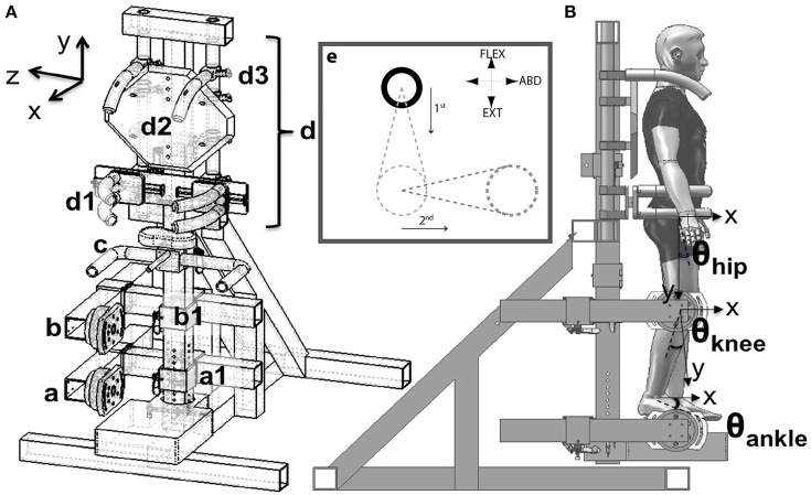
Figure 1.
Schematic of the experimental setup. (Aa,b) Adjustable foot and thigh placement system and JR3 6DoF sensors. (c) Handle bars for accessing the setup. (d) Upper body positioning system. (d1) Hip clamping mechanism. (d2) Back plate. Harness not shown. (d3) Shoulder clamps. (e). Visual display. The cursor (solid circle) could move across the entire plane. The dashed circles and lines indicate the target torque and target trajectory. Participants were requested to first match the vertical distance by generating the corresponding hip flexion/extension or ankle plantarflexion torque. Then, while maintaining the vertical position constant, participants were asked to generate the abduction torque necessary to match the horizontal displacement. The hip abduction torque was then quantified as that generated while the vertical level was constant. The display was adjusted for left/right extremities and flexion/extension torques accordingly such that upward displacement indicated flexion and downward extension, displacement to the left was left hip abduction and vice versa for the right extremity. (B) Angle descriptions, sagittal plane. The hip flexion angle was measured with respect to the projection of the trunk's gravity vector. The knee flexion angle was measured with respect to the thigh. The ankle angle was measured with respect to the shank. The hip abduction angle (frontal plane), was measured with respect to the gravity vector's direction.

