
Table 2. Optimization of the reaction conditions.
| |||||
| Entry | Catalyst | Base | Time | Conversion a | Yield b |
| 1 c , d | 1 | Cs2CO3 | 2 h | >95% | 55% |
| 2 d | 2 | Cs2CO3 | 2 h | 50% | 20% |
| 3 d | 3 | Cs2CO3 | 2 h | 90% | 5% |
| 4 | 4a | Cs2CO3 | 2 h–6 h | 60% | 50% |
| 5 | 4c | Cs2CO3 | 2 h | >95% | 70% |
| 6 | 4c | K2CO3 | 2 h | >95% | 75% |
| 7 | 4c | K2CO3 | 1 h | >95% | 80% |
| 8 | 4d | K2CO3 | 1 h | >95% | 75% |
| 9 | 4b | K2CO3 | 1 h | >95% | 75% |
| 10 e | 4c | K2CO3 | 1 h | >95% | 70% |
| 11 f | 4c | K2CO3 | 1 h | >95% | 80% |
| 12 | 4c | K2CO3 | 0.5 h | >95% | 80% |
| 13 | — | K2CO3 | 1 h | NR | NR |
| 14 | 4c | — | 1 h | <10% | 5% |
| 15 g | 4c | K2CO3 | 1 h | NR | NR |
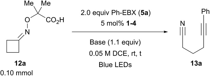
aReaction conditions: using 0.1 mmol 12a (1 equiv.), 0.2 mmol 5a (2.0 equiv.), 5 mol% 1–4 (0.05 equiv.) in DCE (2.0 mL) for 2 h at RT. The conversion of 12a by NMR is given. NR = no reactivity.
bNMR yield using dibromomethane as internal standard.
cUsing 1 mol% of 1.
dUsing 1.0 equiv. of base.
eUsing 1.5 equiv. of 5a.
fUsing 3.0 mol% of organic dye 4c.
gWithout irradiation.