Figure 2.
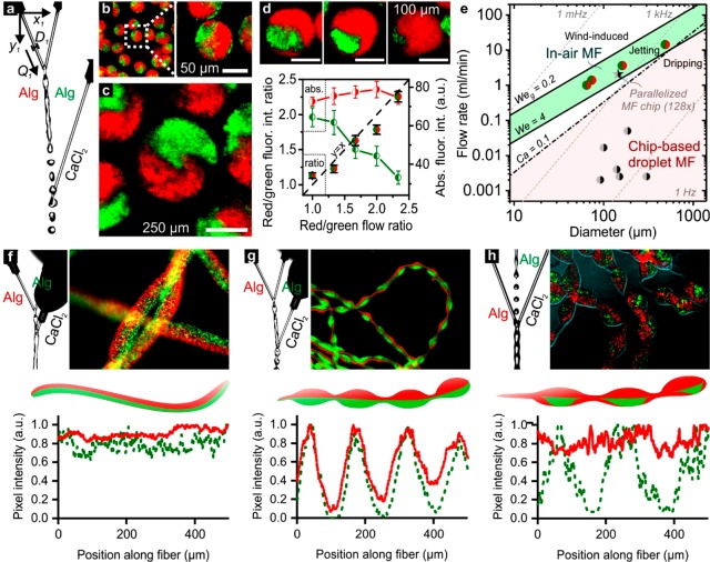
On-the-fly control parameters and throughput. (a) IAMF control parameters include the positions (x,y), diameters (D), and flow rates (Q) of the liquid microjets. The microjet diameters and flow rates could be tuned to change the size of the (b, c) Janus microparticles as well as their (d) individual compartments. (e) Plotting the per-nozzle flow rate as a function of nozzle diameter for in-air and chip-based droplet microfluidics (MF) revealed a significant difference in production throughput. Monodisperse droplet production using chip-based microfluidics relies on dripping. Its production regime is bound by Ca = 0.1 and We = 4, as indicated by the red shade. In contrast, IAMF is based on jetting, which regime is bound by We ≳ 4 and Weg ≲ 0.2, as indicated by the green shade. The green-red circles are data points obtained using our IAMF setup. The black-gray data points are obtained from previously reported studies on droplet microfluidics for Janus microparticle production (Table S1). The corresponding droplet production frequencies are indicated with gray dashed lines. (f) Positioning the Ca2+ containing cross-linker microjet upstream of the alginate containing solid precursor microjets’ breakup point resulted in the formation of a Janus microfiber. Alternative positioning resulted in periodically (g) beaded and (h) patched Janus microfibers.

