
Fig. 7.
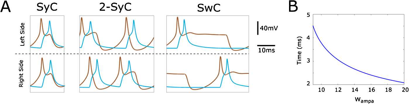
(A) Time evolution of the voltage of dINs (brown lines) and cINs (blue lines) during one period of synchrony (SyC), double-synchrony (2-SyC) and swimming (SwC). The three limit cycles are detected by AUTO in Fig. 6. Synaptic strength parameters used to generate each panel SyC, 2-SyC and SwC, respectively, are nS, 45 nS and 40 nS. (B) Time difference between left dIN and left cIN spikes during one cycle of the SwC at varying . The remaining vector of parameters used to obtain this figure are nS, nS, ms and ms