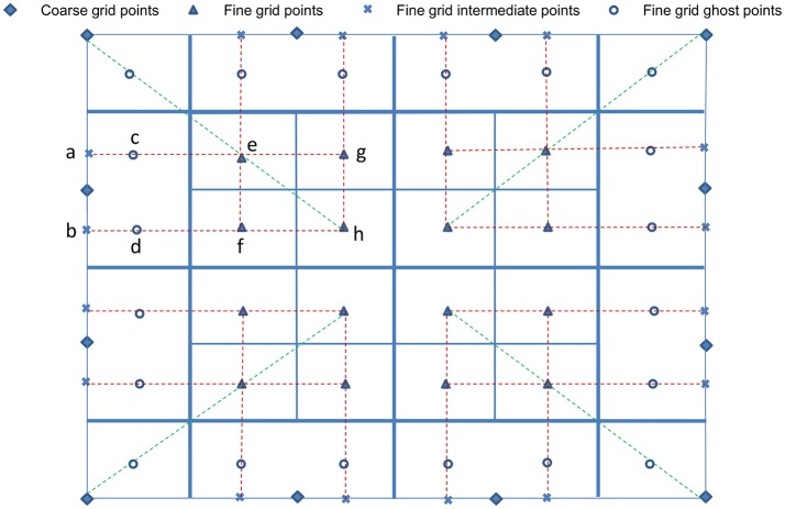
Figure 3.
Interpolation at fine-grid ghost layers. For simplification and ease of visualization, a two dimensional illustration is presented. The coarse grid mesh is shown using thick solid lines, and the finer grid mesh is shown using thin solid lines. The internal cell-centered grid points of the finer grid are depicted by (▴) and its external/ghost grid points are represented by (°). Only relevant cell-centered grid points (♦) on the coarse grids are shown. First, data on intermediate points (×) are obtained using quadratic interpolation from their nearest three coarse grid points (♦). Corner ghost cells (°) are obtained by quadratic interpolation using the nearest coarse-grid data (♦) and two fine-grid data (▴) on the diagonal, shown by green dashed lines. Remaining ghost cells (°) are obtained from the intermediate points (×) and two fine-grid interior points (▴), shown by red dashed lines.

