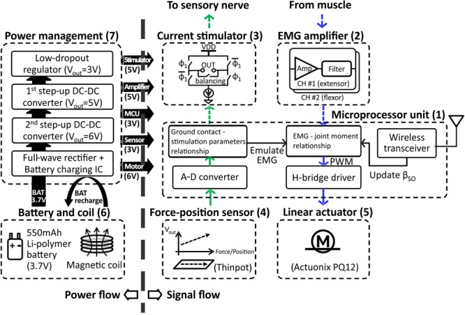
FIGURE 1.

Block diagram illustrating power flow (on left) and signal flow (on right) between prosthetic components. The sensory pathway of signal flow on right is indicated by the green arrows; the motor pathway is indicated by blue arrows. The pathways represented by dashed arrows are not implemented in the prosthetic prototype, but will be implemented when the prosthesis is worn by the cat. See text for details.
