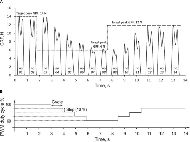
FIGURE 6.

Ground reaction force (GRF) during 14 cycles of prosthesis loading (A) and the corresponding changes in PWM duty cycle of the actuator (B). The three target values of GRF peak (14, 6, and 12 N) are indicated by the horizontal dashed lines in (A). The numbers at bottom of force traces indicate the cycle number. For details, see text.
