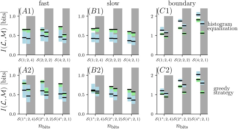
Fig 5. Mutual information for different encoding strategies based on two sensors.
Eight bits are assigned in three different strategies to two sensors. The blue shaded region marks the mutual information for the narrow grid and the green shaded region marks the mutual information for the wide grid (black lines for centered locations, shaded regions for jittered locations). For each strategy, the left columns (white region) correspond to a sensor alignment transversal to the centerline of the imaged area. The right columns (gray shaded region) correspond to a sensor alignment longitudinal to the center line. The first row (A1—C1) corresponds to chosing bins boundaries with histogram equalization, the second row (A2—C2) corresponds to chosing bin boundaries according to the “greedy” method as explained in the text.

