Fig. 1.

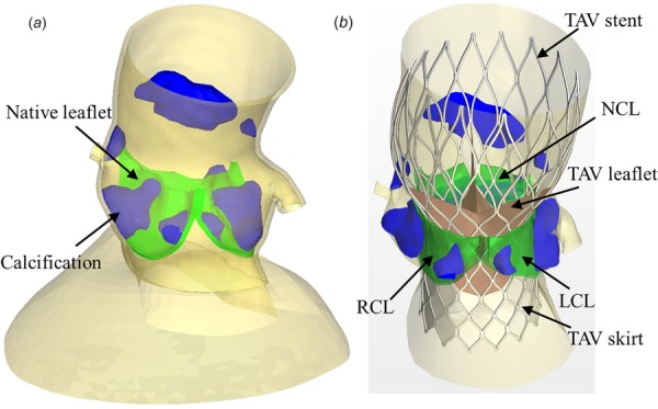
(a) Pre-TAVR aortic root geometry from CT scans used for FE simulations of TAV deployment and (b) post-TAVR geometry obtained from FE simulation results. TAV skirt and leaflets were added to accommodate CFD simulations.

(a) Pre-TAVR aortic root geometry from CT scans used for FE simulations of TAV deployment and (b) post-TAVR geometry obtained from FE simulation results. TAV skirt and leaflets were added to accommodate CFD simulations.