. 2018 Jul 23;7:e37342. doi: 10.7554/eLife.37342

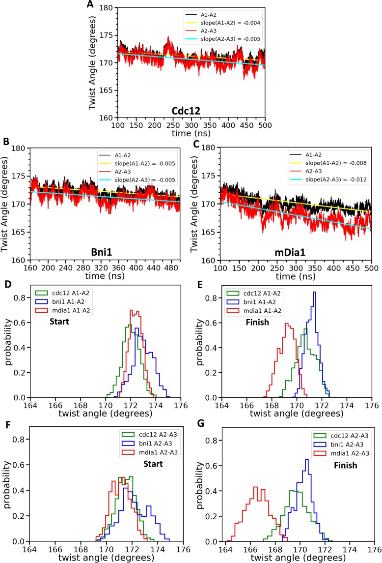
Figure 4. Effect of FH2 domains on the barbed end configurations of actin seven-mer filaments.

The panels show helical twist angles between subunits at the barbed ends of actin filaments associated with three different formin FH2 dimers during all-atom MD simulations. (A–C) The angles between the actin subunits (A1–A2 and A2–A3) as a function of time. The measurements start after initial equilibrations (Figure 2) at 100 ns for Cdc12 and mDia1 or at 160 ns for Bni1. (D–G) Comparison of the distributions of angles between actin subunits A1-A2 and A2-A3 during two different time intervals. (D, F) t = 100–150 ns for Cdc12 and mDia1, and t = 160–210 ns for Bni1. (E, G) t = 450–500 ns for all systems.

Figure 4—source data 1. Twist angles between actin subunits as a function of time.
Helical twist angles between subunits of seven-mer filaments (A1–A2, A2–A3, A3–A4, A4–A5 and A5–A6) associated with three different formin FH2 dimers during all-atom MD simulations. The angles are outputted at every 40 ps during the time intervals given in Figure 4.
DOI: 10.7554/eLife.37342.013

Figure 4.

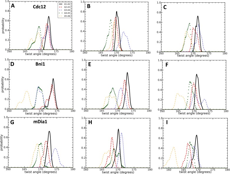
Figure 4—figure supplement 1. Effect of FH2 domains on the configurations of actin seven-mer filaments.

Figure 4—figure supplement 1.

Comparison of the distributions of angles between the actin pair of subunits during three different time intervals. (A,D,G) t = 100–120 ns for Cdc12 and mDia1, and t = 160–180 ns for Bni1. (B,E,H) t = 280–300 ns for all systems. (C,F,I) t = 480–500 ns for all systems.