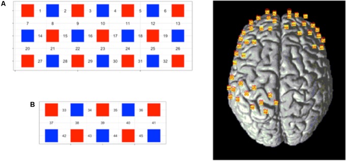
FIGURE 3.
Schematic representation of the 45-channel fNIRS probe sets placed on the participants’ scalps, separated into the frontal lobe [(A) block, channels: 1—32] and occipital lobe [(B) block, channels: 33–45]. Red squares represent light emitters, blue squares represent detectors, and numbers represent the measurement channels. Cranial optode channels in relation to the underlying anatomical structures are shown for one representative subject.

