
Figure 2. Illustration of the steps in image processing to quantify pillar displacements.
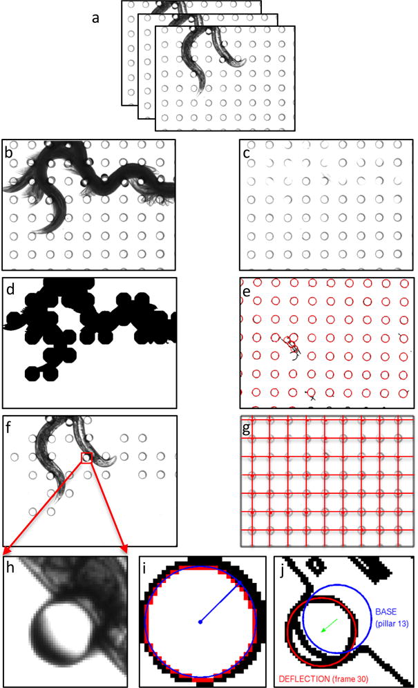
(a) Original images of a crawling worm. (b) Foreground image and (c) background image from a stack of images in the preprocessing step. (d) Mask generation from the foreground. (e) Identification of all pillars by applying circular Hough transform. (f) Identification of the candidate pillar for tracking using the mask. (g) Grid verification and validation of pillar location. (h) A candidate pillar selected from a frame (see red arrows) for illustration of deflection measurement. (i) Determination of pillar base location and radius when the worm is not touching the pillar. (j) Measurement of pillar displacement.