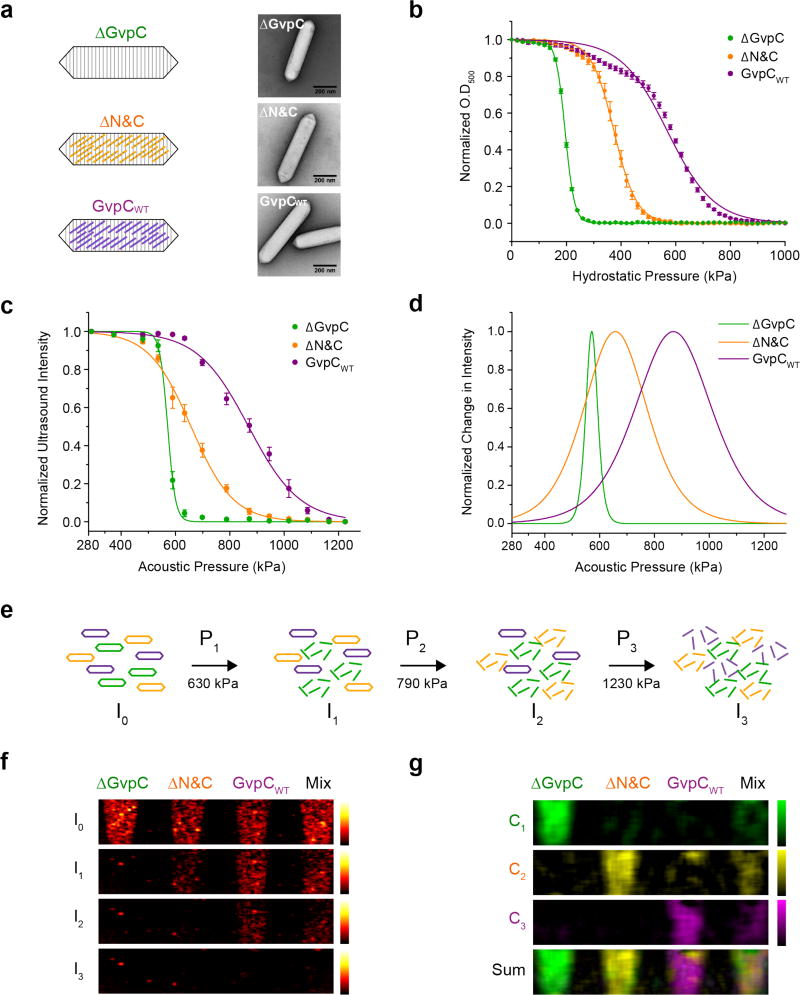
Figure 2. GvpC engineering enables tuning of GV collapse pressure for acoustic multiplexing.
(a) Schematic illustration of the three engineered GV variants used for acoustic multiplexing. ΔGvpC, ΔN&C and GvpCWT variants are represented by green, orange and purple colors respectively. Accompanying TEM images show the conservation of GV shape among the three variants (scale bars are 200 nm). (b) Optical density measurements of engineered Ana GVs as a function of hydrostatic pressure (N=7 independent preparations, error bars are SEM). The data was fitted with a Boltzmann sigmoid function. Fit parameters and R2 values are provided in Table S1. (c) Acoustic collapse curves for the GV variants showing normalized ultrasound signal intensity as a function of increasing peak positive pressure from 290 kPa to 1.23 MPa (N= 3 independent trials, error bars are SEM). The data was fitted with a Boltzmann sigmoid function (parameters provided in Table S2), the derivatives of which with respect to pressure are plotted in (d). (e) Schematic illustration of acoustic spectral unmixing, showing serial collapse of the GV variants based on their critical collapse pressure and indicating the pressures used in panels f and g. (f) Ultrasound images of an agarose phantom containing wells with ΔGvpC, ΔN&C, GvpCWT and a mixture of the three variants (all GVs at final OD 1.0 in PBS), acquired at 6.25 MHz. I0; before collapse I1: after collapse at 630 kPa I2: after collapse at 790 kPa I3: after collapse at 1230 kPa. (g) Spectrally unmixed images processed from the raw ultrasound data in (f). The bottom panel shows an overlay of the three unmixed channels C1, C2, and C3.

