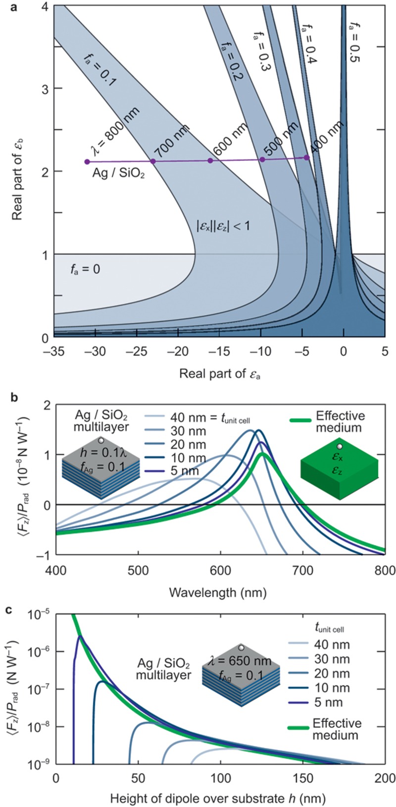
Figure 3.

Repulsive force from metal–dielectric stacks. (a) Range of permittivities of the material constituents of the multilayer required to achieve repulsive force on the emitter in air in the effective medium approximation and neglecting material losses. Shaded areas correspond to the repulsive force for different filling fractions of the multilayer. If losses were increased, the shaded areas would become narrower and eventually disappear. Notice that when fa=0 (no material ‘a’), the repulsive condition becomes |εb|<1, corresponding to the known repulsion condition for an isotropic substrate. The horizontal line labelled Ag/SiO2 follows the permittivities of Ag and SiO2 layers at different wavelengths. (b) The spectral dependence of the force acting on a dipole at a height h=0.1λ above an Ag/SiO2 semi-infinite multilayered metamaterial with fAg=0.1 calculated using Equation (1) for different unit cell sizes, and for the equivalent homogeneous anisotropic effective medium. The low loss of silver in the visible spectral range56
 allows the bandwidth of repulsion to almost match exactly that of the lossless case shown in a. (c) The height dependence of the force acting on a dipole at the wavelength of λ=650 nm. All other parameters are as in b.
