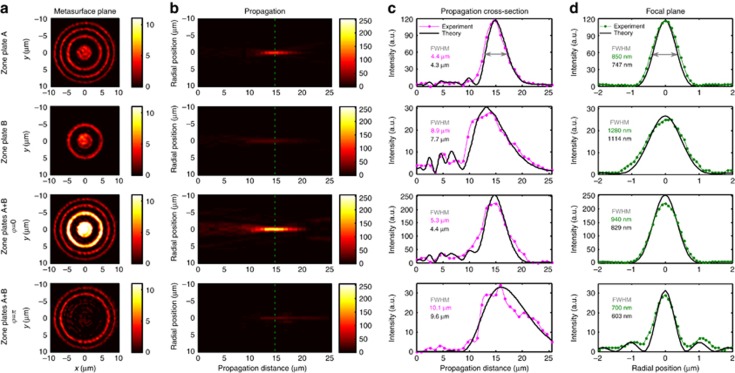
Figure 4.
Controlling focal depth and diameter by projecting different Fresnel zone plate patterns, A (row 1) and B (row 2) onto opposite sides of the metasurface. Results in rows 1 and 2 were recorded by illuminating only one zone plate (as in Figure 3). Constructive interference of transmitted and reflected lens patterns leads to a short, high-intensity focus (φ=0, row 3), while destructive interference leads to a dimmer, narrower Bessel-beam-like focus with a large focal depth (φ=π, row 4). (a) Images of the metasurface plane taken with a camera when zone plate(s) are projected onto the metasurface. (b) Measured light distribution at different distances z from the metasurface (yz-plane) with the focal plane indicated by a dashed line. (c) Intensity distribution along the optical axis. (d) Radial intensity distribution on the focal plane at z=15 μm, obtained by averaging cross-sections along x and y. All color scales show intensity. See Supplementary Fig. S3 for more details.

