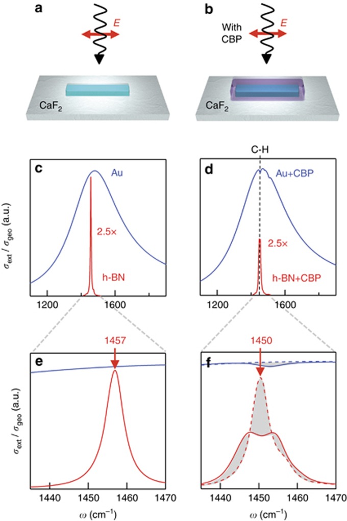
Figure 1.
Numerical comparison between an h-BN and a Au resonator. (a and b) Sketches of the system designed for simulations: a h-BN (or Au) rod is placed on top of a CaF2 substrate and illuminated by a plane wave, with E-field being polarized along the main axis of the rod. (c and d) Extinction cross-section normalized to the geometrical cross-section for the h-BN (red) and the Au (blue) rod antenna without and with a 5-nm-thick layer of CBP on top, respectively. The full-wave electromagnetic simulations use the dielectric functions of Au, h-BN and CBP as described in the Materials and methods section. Note that for better comparison we scaled the h-BN antenna spectra by a factor 2.5. (e and f) frequency zoom-in (of c and d). Dashed lines in f represent calculated reference spectra for Au (blue) and h-BN (red) antennas, assuming a 5-nm-thick homogeneous dielectric layer with ε=ε∞=2.8 placed on top of the antennas. Gray areas highlight the spectral changes due to the interaction of the CBP vibration (C–H bond) with the plasmon-polariton resonance in the Au antenna and the phonon-polariton resonance in the h-BN antenna, respectively.

