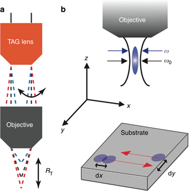
Figure 1.
(a) Experimental setup of the system. The laser beam is guided through the TAG lens and objective before being focused onto the substrate. The TAG lens is an ultrafast vari-focal device that generates sine wave oscillations in lens power (a quantity that is linearly dependent on the driving voltage). These oscillations result in variations in the focal position below the objective, which we call the laser scanning range, or RT. (b) In this paper, we adopt the convention that the laser beam travels in the negative z direction. The beam waist is shown as a curved black line; the position at which the beam waist is narrowest defines the focal point. Ablation occurs when the fluence is larger than the threshold fluence. The blue circle indicates the region in which ablation occurs: the ablation range. The bottom diagram shows the line scan path during the milling experiment, where the blue circles represent the focused beam location and the red lines indicate the beam path along the substrate.

