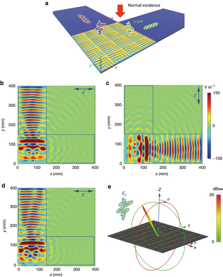
Figure 3.
Demonstration for the independent controls of SWs using anisotropic coding metasurfaces under normal incidence at 10 GHz. (a) Schematic illustration for the simulation configuration of spatial-to-surface-wave conversion. (b, c) Electric-field distributions for coding pattern M2 under the x- and y-polarizations, respectively. (d) The electric-field distribution (Ex) under the x-polarized illumination when the coding matrix is M3. (e) The far-field pattern under the y-polarized illumination when the coding matrix is M3.

