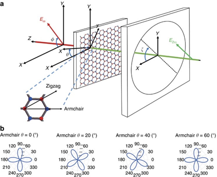
Figure 2.
(a) Coordinate system describing the experimental measurements and introducing relevant angles with respect to the laboratory frame; φ, angle between excitation linear polarization Eω and X-laboratory axis; θ, angle between TMD armchair crystal orientation -x and the X-reference axis; ζ, angle between linear polarizer axis and X-axis. The crystal structure and symmetry axis of WS2 are shown (top view) magnified. (b) Simulation of the PSHG intensity modulation as a function of the linear excitation angle φ, described by Equation (1), for four different armchair orientations, θ=0°, 20°, 40° and 60°, when ζ=0. Note that for a fixed position of the analyzer, the fourfold symmetric polar diagram of the SHG intensity rotates as a function of the armchair crystal orientation.

