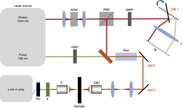
Figure 3.
Optical setup for SS-SRS. Spectroscopic SRS imaging is achieved by tuning the temporal delay of the chirped Stokes beam and pump beam. A glass rod is applied for the chirping pulses. Temporal delay is added by directing the Stokes beam at the edge of GM1. Together with GM2 and GM3 for spatial positioning of the combined laser beams, the 3D high-LCM triangular Lissajous scanning trajectory is generated. AOM, acousto-optic modulator; C, condenser; F, filter; HWP, half-wave plate; L, lens; M, mirror; OBJ, objective; PBS, polarizing beam splitter; PD, photodiode; QWP, quarter-wave plate.

