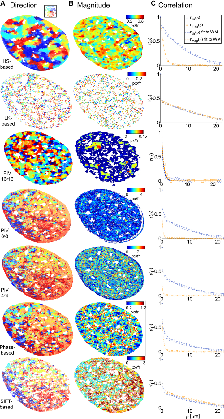
Figure 3.
Visualization of flow fields for the analysis of a single U2OS cell expressing H2B-GFP. Rows correspond to the different investigated methods. Representative fields are shown. (A) Flow fields are color-coded by the direction of displacement vectors. (B) Magnitude of the corresponding flow vector color-coded from low to high as indicated by color bars. (C) Empirical correlation for direction (blue) and magnitude (orange) and corresponding fits to the WM model (solid lines) over space lags.

