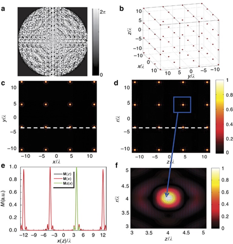
Figure 5.
The 4 × 4 × 4 3D super-resolution longitudinal MS array induced by the optimized MPFs acting on the left-handed circularly polarized BG beams in the 4π focusing geometry. (a) Phase pattern of the MPFs with G=S=T=4 and ag=bs=ct=8λ. (b) 3D iso-magnetization surface of the MS array with M=Mmax/2. (c and d) Contour plots of the total magnetization field in the xy and rz planes. (e) Relevant magnetization cross-section profiles in c and d, respectively (black and red lines are along the x and z axes, respectively. The green line represents the x axis cross-section of the magnetization pattern of a single focal spot without the use of MPFs. (f) Enlarged individual spot inside the MS array and its polarization distribution in the rz plane.

