Abstract
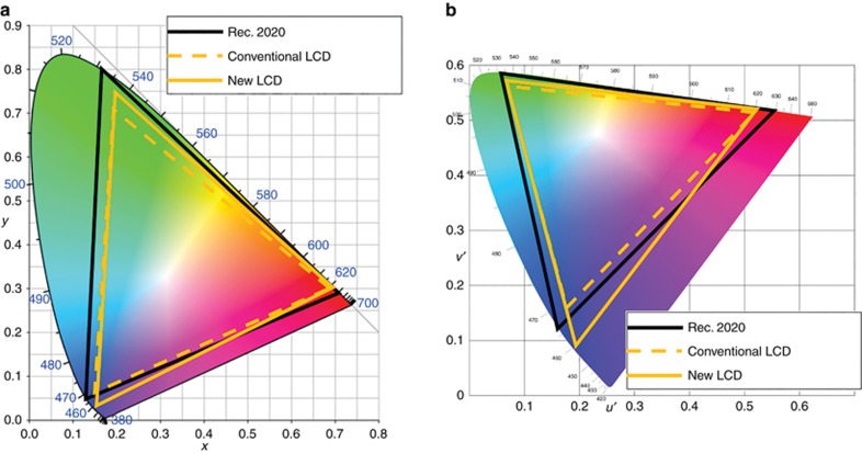
In this study, we analyze how a backlight’s peak wavelength, full-width at half-maximum (FWHM), and color filters affect the color gamut of a liquid crystal display (LCD) device and establish a theoretical limit, even if the FWHM approaches 1 nm. To overcome this limit, we propose a new backlight system incorporating a functional reflective polarizer and a patterned half-wave plate to decouple the polarization states of the blue light and the green/red lights. As a result, the crosstalk between three primary colors is greatly suppressed, and the color gamut is significantly widened. In the experiment, we prepare a white-light source using a blue light-emitting diode (LED) to pump green perovskite polymer film and red quantum dots and demonstrate an exceedingly large color gamut (95.8% Rec. 2020 in Commission internationale de l'éclairage (CIE) 1931 color space and 97.3% Rec. 2020 in CIE 1976 color space) with commercial high-efficiency color filters. These results are beyond the color gamut limit achievable by a conventional LCD. Our design works equally well for other light sources, such as a 2-phosphor-converted white LED.
Keywords: color gamut, liquid crystal displays, perovskite, polarization, quantum dot
Introduction
The liquid crystal display (LCD) has become ubiquitous in our daily lives. Widespread applications range from smartphones, tablets and computer monitors to TVs, just to name a few1. An essential requirement for display devices is an accurate representation of color. To widen the color gamut of an LCD, a straightforward approach is to employ a backlight with highly saturated red, green and blue (RGB) primary colors2. Generally, a light source with a narrower full width at half maximum (FWHM) would lead to a wider color gamut3. During the past two decades, LCD backlights have evolved from blue-pumped yellow YAG: Ce3+ phosphor-converted white-light-emitting diodes (1pc-WLED: FWHM ~120 nm) to green and red phosphors-converted WLEDs (2pc-WLED: FWHM ~50 nm) and to quantum dots (QDs: FWHM ~25–30 nm)4, 5, 6, 7, 8. Recently, organic–inorganic perovskite (OIP) was found to have a narrower FWHM (~18–20 nm) than that of QDs9, 10. As a result, it holds potential to further enhance the color gamut of an LCD. However, an interesting question to ask is: Is there a theoretical limit to the color gamut of an LCD, even if the FWHM of the light-emitter approaches zero, or <1 nm, such that of lasers?
In addition to backlighting, a narrow-band color filter (CF) is another option that can be used to enlarge the color gamut, except that its optical efficiency is compromised11. State-of-the-art QD-enhanced backlights, along with specially designed narrow-band CFs, could achieve 92% Rec. 2020 (Ref. 12), but the tradeoff is ~25% reduced efficiency. For a battery-powered display, this 25% light efficiency loss is hardly acceptable. Therefore, new approaches to achieve a wide color gamut that maintain high optical efficiency are urgently needed.
In this paper, we first investigate how the FWHM of a light source affects the gamut of LCD colors and find a theoretical limit, even if FWHM approaches 1 nm. Next, we propose a new backlight system incorporating a functional reflective polarizer (FRP) and a patterned half-wave plate to suppress the crosstalk originating from CFs, which in turn significantly widens the color gamut. In the experiment, we prepare a white-light source using a blue light-emitting diode (LED) to pump green OIP-polymer composite film and red QD and demonstrate an exceedingly wide color gamut, with 95.8% Rec. 2020 in Commission internationale de l'éclairage (CIE) 1931 color space and 97.3% Rec. 2020 in CIE 1976 color space, using commercial high-efficiency CFs. Our result is comparable to that of laser projection displays but with direct-view LCD panels. In addition to QDs and perovskites, our design also works well for other light sources, such as 2pc-WLED.
Materials and methods
Before evaluating the color gamut of an LCD, let us first elucidate its definition, as this definition is sometimes confusing and misleading. Several standards have been proposed to quantify color gamut (for example, sRGB, Adobe RGB, NTSC and so on). Here we focus on the most comprehensive standard, called Rec. 2020, with RGB lasers. Rec. 2020 covers all the existing standards13, 14, 15, 16. Next, we define the coverage ratio rather than the area ratio as the color gamut. Under this definition, the obtained color gamut should not exceed 100% Rec. 2020. Another important thing to choose is the right color space, CIE 1931 or CIE 1976 (Refs. 17, 18). Although CIE suggests using CIE 1976, as it is a color uniform space, many display makers and research groups are still using CIE 1931 to display their results. To satisfy both camps, here we present a color gamut in both CIE 1931 and CIE 1976.
Gaussian-fitting effect
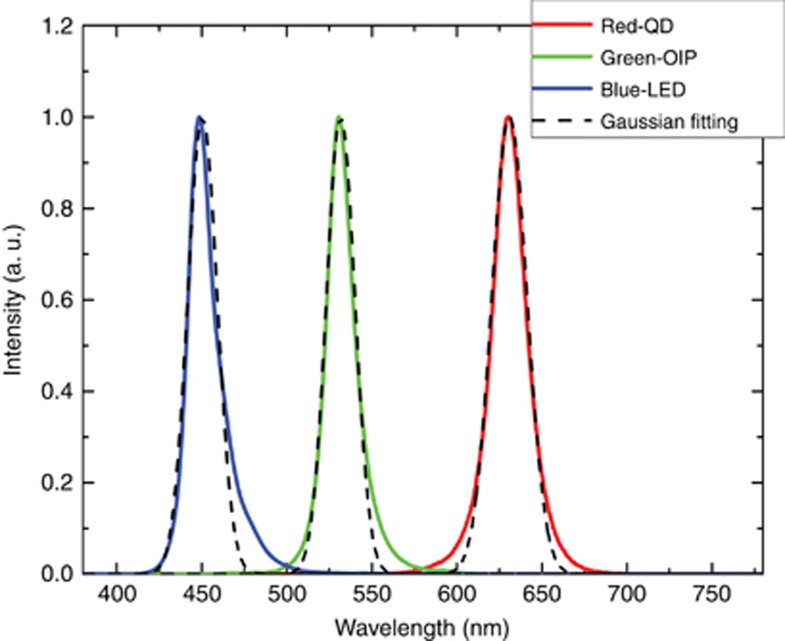
Figure 1 demonstrates the measured spectra of blue LED, green OIP and red QD; all exhibit Gaussian-like profiles. Thus, Gaussian fitting is commonly conducted to extract the peak emission wavelength and FWHM. These fitted curves are then employed to calculate the color gamut by neglecting the fitting discrepancy3, 11, 17, 19. Through fittings, we obtained the peak wavelength and FWHM of three primary colors as follows: λB=450.4 nm, ΔλB=20.3 nm; λG=531.6 nm, ΔλG=19.7 nm; and λR=630.8 nm, ΔλR=24.4 nm, respectively. From Figure 1, a noticeable discrepancy is observed, especially for the blue LED. The red QD and green OIP present longer emission tails than the fitted Gaussian functions. As will be shown later, these tails aggravate the color crosstalk, which in turn shrinks the color gamut.
Figure 1.
Emission spectra for blue LED and green perovskite and red QD. Solid lines are measured data and dashed lines are from Gaussian fittings.
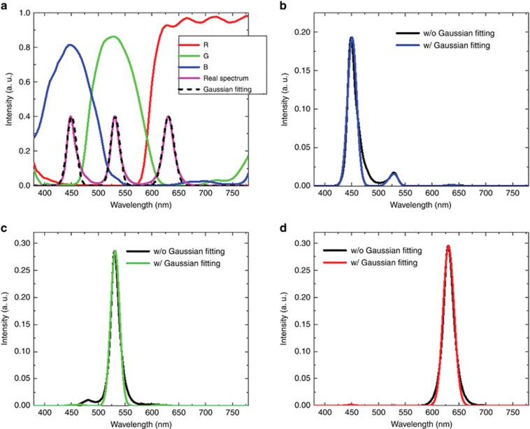
In an LCD, the backlight passes through the LC layer and CFs before reaching the viewer. Therefore, we have to incorporate the backlight spectra (Figure 1) into the LCD panel to calculate the output spectral power distribution (SPD)20. In our simulation, we have chosen a fringe field switching LCD with negative dielectric anisotropy (Δε<0) LC21, 22 and a commercial CF array11 as an example (Figure 2a). Such an LCD has been widely used in smartphones and pads. The wavelength-dependent refractive indices of the employed LC are also considered in the simulation. Figure 2b–2d depicts the obtained SPD for the RGB primary colors with or without Gaussian fitting. In both cases, light leakage for all three channels is observed clearly, especially for the blue channel, where a fairly large bump leaks through the green CF. For the real spectrum without Gaussian fitting, the light leakage is even worse, owing to the long-emission tails, which further deteriorate the color purity.
Figure 2.
(a) Transmission spectra for a commercial CF array. Output SPDs for (b) blue, (c) green and (d) red primary colors with and without Gaussian fitting.
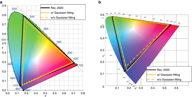
Figure 3 illustrates the color gamut shrinkage more clearly. In both color spaces, green and blue color coordinates with Gaussian fitting expand outward, representing high purity primary colors. The obtained color gamut results are summarized in Table 1.
Figure 3.
Color gamut in (a) CIE 1931 color space and (b) CIE 1976 color space.
Table 1. Simulated color gamut for the light source with and without Gaussian fitting.
| Rec. 2020 |
||
|---|---|---|
| CIE 1931 | CIE 1976 | |
| w/ Gaussian fitting | 89.4% | 89.9% |
| w/o Gaussian fitting | 82.8% | 83.9% |
In the CIE 1931 color space, the color gamut with Gaussian fittings is 6.6% wider than that using the real spectra, whereas in CIE 1976, this difference is 6%. For different CFs and light sources, this discrepancy varies. However, Gaussian-fitted curves lead to a wider color gamut than using the real emission spectra. Therefore, to establish the theoretical limit of the color gamut of an LCD, we use the Gaussian-fitted spectra.
Pareto front for the color gamut and light efficiency
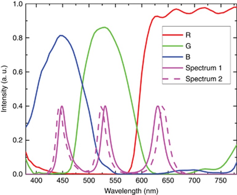
From Table 1, the color gamut without Gaussian-fitted spectra is ~83% Rec. 2020. To improve that, we fine-tuned the emission spectrum of QD and OIP to match the transmission bands of CFs, as Figure 4 demonstrates. However, tuning the peak emission wavelength influences the light efficiency, because the human eye has different sensitivities to different colors. This is governed by the human eye sensitivity function V(λ), which peaks at 555 nm. Therefore, we introduced another metric, the total light efficiency (TLE), to characterize how much input light transmits through the LCD panel and finally gets converted to the brightness perceived by the human eye3:
Figure 4.
Transmission spectra of commercial CFs and different white-light sources.
In Equation (1), Sin(λ) is the SPD of the light source (that is, input backlight) and Sout(λ) represents the output SPD after the LCD panel.
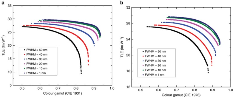
Both color gamut and TLE are important parameters for a display device. For such a multi-objective problem, different objectives may be mutually exclusive. In short, any further improvement of one objective (for example, color gamut) is likely to be compromised by the degradation of another objective (for example, TLE). Therefore, a Pareto front is commonly employed, and all solutions will fall either on or below this Pareto front (see Supplementary Information for more details). Figure 5 is a plot of the calculated Pareto fronts of the LCD using backlight with different FWHM values.
Figure 5.
Pareto front defined in (a) CIE 1931 and (b) CIE 1976 with different FWHM light sources.
From Figure 5, several interesting phenomena are observed. First, there is an inherent tradeoff between light efficiency and color gamut. Thus, a delicate balance should be chosen in practical applications. Second, for a backlight with the same FWHM, there is indeed a theoretical limit for the color gamut, regardless of the RGB central wavelengths. For example, when the FWHM of QD or OIP emission spectrum is 30 nm, the largest achievable color gamut is 90.1% Rec. 2020 in CIE 1931 (Figure 5a) or 91.5% Rec. 2020 in CIE 1976 (Figure 5b). Next, we find that as the light source becomes more saturated (that is, a narrower FWHM), the maximum color gamut increases and then gradually saturates. Currently, the commercial Cd-based QD-enhanced backlight exhibits a 30-nm FWHM, and it could reach 25 nm in the next few years7. Assuming that 20 nm can be obtained someday, according to Figure 5, the color gamut improvement is only 2%. Even if the FWHM of the light emitters were laser-like (≤1 nm), the maximum color gamut is ~93.5% Rec. 2020. This limits the color gamut that an LCD can possibly achieve. Please note that this limit is obtained with Gaussian-fitted spectra; it would be lower if real spectra are used.
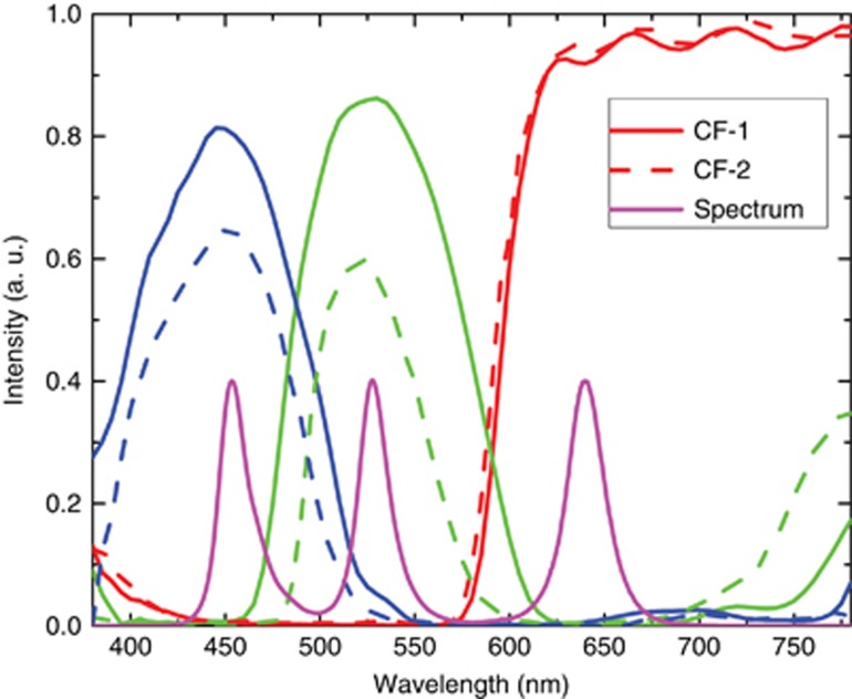
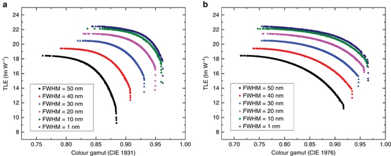
Next, we examine the CF effect, as shown in Figure 6. The results shown in Figure 5 are based on CF-1; it has high transmittance, but a relatively large overlap in the blue/green and green/red regions. Alternatively, CF-2 possesses a smaller crosstalk, but the transmittance is ~25% lower in the blue and green regions. Again, we carry out the optimizations using CF-2 and plot the Pareto front results, which are shown in Figure 7. The trend is similar to that in Figure 5, but it has a wider color gamut. Due to the suppressed light leakage, the color gamut reaches 93.1% Rec. 2020 when a 30-nm FWHM backlight is employed. If we reduce the FWHM to 20 nm, this limit is increased to 94.9% Rec. 2020. However, when the real spectrum is employed, the color gamut should be narrower due to the above-mentioned Gaussian-fitting effect. In comparison with CF-1 (Figure 5), CF-2 suffers 25% in optical efficiency but only gains 2.7% in color gamut. Such a tradeoff may not be worthwhile, especially for battery-powered mobile display devices.
Figure 6.
Transmission spectra of two commercial CFs and a white-light source.
Figure 7.
Pareto front defined in (a) CIE 1931 and (b) CIE 1976 using CF-2.
We have found the theoretical limit of the color gamut of an LCD, as shown in Figures 5 and 7. It is jointly determined by the light source (central wavelength and FWHM) and the CFs (crosstalk). Even if we reduce the FWHM of the backlight to 1 nm, the color gamut is still limited by the crosstalk of the blue/green and green/red CFs (Figure 2). Narrowing the transmission bands (CF-2) could mitigate this issue but not completely. Meanwhile, the optical efficiency is substantially compromised. This tradeoff may not be worthwhile. Therefore, as long as the CF technology makes no disruptive progress, the color gamut of an LCD will be limited, even if the backlight source exhibits laser-like narrow emission spectra.
Results and discussion
New device configuration
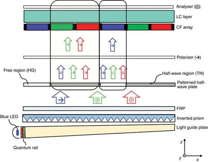
From the above discussions, narrowing the emission spectrum of QD or OIP would eventually reach the theoretical limit, on the basis of the predictions presented in Figures 5 and 7. To overcome the barrier resulting from CFs, we propose a new backlight configuration, which is depicted in Figure 8. The key components are a FRP and a patterned half-wave plate. They work together to suppress unwanted light leakage caused by CFs.
Figure 8.
Schematic diagram and working principle of the proposed backlight with an FRP and a patterned half-wave plate. Abbreviations: HG, homogeneous alignment; TN, twisted nematic alignment.
From Figure 8, a high power blue LED is used to excite the quantum rail, consisting of red QD and green OIP-polymer composite film. The light guide plate, together with an inverted prism film, forms a directional backlight23 that is combined with a front diffuser (not shown here). Such a system offers several advantages, including wide viewing angle, negligible color shift and unnoticeable gamma shift24. Our FRP and patterned half-wave plate can be laminated on the top surface of the inverted prism film.
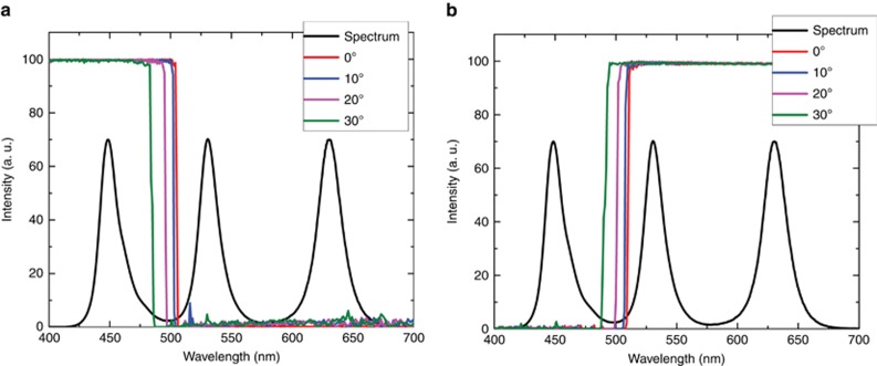
The design principles and working mechanisms of an FRP have been reported in Ref. 25. Briefly speaking, an FRP is a multi-layer structure with alternative refractive indices (n1 and n2), as shown in Supplementary Fig. S1. Due to the constructive/destructive interferences, it functions as a bandpass filter for both polarization directions (that is, x-polarized and y-polarized). For x-polarized incident light (Figure 9a), only short-wavelength light (blue) can pass, whereas the rest is reflected. For y-polarized incident light (Figure 9b), it is reversed: only green and red lights can pass through an FRP, whereas blue light is reflected. As a result, after the FRP, the polarization state of blue light is orthogonal to that of green/red lights (Figure 8). The detailed design procedures can be found in Supplementary Information. In general, our FRP is a multi-layer film with a total thickness of 23.6 μm. We also studied the angular-dependent transmission of our FRP, and the results are shown in Figure 9a and 9b. Within ±30° incidence, our FRP could still effectively separate the blue and green/red regions. For a commercial directional backlight (with FWHM ~20°, that is, ±10°), the optical power is mostly confined within ±20° (Ref. 23). Therefore, our FRP works quite well, regardless of the small band shift.
Figure 9.
Angular-dependent transmission spectra of (a) x-polarized incident light and (b) y-polarized incident light.
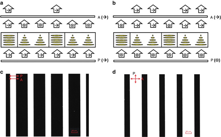
The above FRP is a patterned phase retardation film, which is divided into a half-wave region and a free region. For light traversing through the λ/2 region, the polarization is rotated by 90°, for example, x-polarization turns into y-polarization or vice versa. If the light passes through the free region, then the polarization remains unchanged. To achieve this goal, we employed a patterned LC phase retardation film26, 27, 28. In the λ/2 region, the LC has a 90° twist, whereas in the free region, it has homogeneous alignment20, 29. The detailed structure and working principle are illustrated in Figure 10a and 10b. With the help of photoalignment technology, we have successfully fabricated a patterned half-wave plate (see Supplementary Information for details). The captured polarized optical microscope images under parallel and crossed polarizers are shown in Figure 10c and 10d, respectively. As expected, the patterned half-wave plate performs quite well.
Figure 10.
Working principle of a patterned half-wave plate for (a) x-polarized incident light and (b) y-polarized incident light. Captured polarized optical microscope images under (c) parallel polarizers and (d) crossed polarizers. Scale bar=50 μm. Abbreviations: A, analyzer; P, polarizer.
For the system configuration shown in Figure 8, this patterned half-wave plate should register with the RGB sub-pixels. Here the half-wave region is right below the green/red sub-pixels, and the free region corresponds to the blue sub-pixel. After the FRP, the blue light is polarized along the x-axis, whereas the green and red lights are polarized along the y-axis. After passing through the patterned half-wave plate, no change occurs to the light in the free region (corresponding to blue sub-pixel), which indicates that blue light is still polarized along the x-axis. Alternatively, in the half-wave region (corresponding to green and red sub-pixels), the polarization of outgoing light changes 90°, turning the light into y-polarized blue light and x-polarized green/red lights. Therefore, RGB lights could traverse through the front linear polarizer (with transmission axis along x-axis) and enter the corresponding RGB sub-pixels. Please note that only blue light can enter the blue sub-pixels and green/red lights are absorbed by the linear polarizer due to mismatched polarization. A similar situation occurs with the green and red sub-pixels. Therefore, no crosstalk exists between the blue and green/red regions, leading to a much wider color gamut.
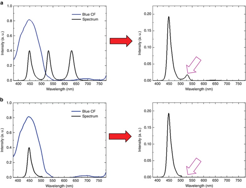
Figure 11 illustrates this effect. Let us assume the LCD backlight spectrum is shown in Figure 1. When the input white light (black line in Figure 11a) passes through blue CF (blue line), there is noticeable light leakage in the green region (500–550 nm), which in turn deteriorates the color purity. However, for our new structure with a patterned half-wave plate, blue light and green/red lights are decoupled in terms of polarization direction. As discussed above, only blue light can enter the blue CF; the crosstalk in the green region is almost completely eliminated (Figure 11b). Similarly, more saturated green and red primary colors are realized. Thus, the color gamut is enhanced from 82.8% to 89.0% Rec. 2020.
Figure 11.
Output SPD of blue primary color for (a) a conventional backlight and (b) the newly proposed backlight.
Going beyond the limit of an LCD’s color gamut
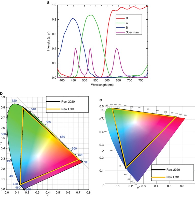
With the white-light source shown in Figure 1, we can obtain 89% Rec. 2020. To further improve this percentage, we need to carefully choose the RGB central wavelengths. In the experiment, we tried multiple combinations of blue LEDs, green OIP and red QDs to generate the desired white light. For detailed material synthesis processes, readers can refer to Section 3 of the Supplementary Information. If we use Gaussian-fitted spectra, then it is fairly easy to simulate the color gamut before searching for suitable light source. However, the actual emission spectrum often contains a long tail, and it is challenging to accurately predict the final color gamut. After dozens of experiments, we have found an optimal combination, as plotted in Figure 12a. The RGB color coordinates overlap quite well with the Rec. 2020 standard, as Figure 12b and 12c shown. The corresponding color gamut is 95.8% Rec. 2020 in CIE 1931 and 97.3% Rec. 2020 in CIE 1976. Here a high-efficiency CF (CF-1 in Figure 6) is employed. Compared to the theoretical limit (93.5% Rec. 2020 for 1-nm FWHM) shown in Figure 5, we have successfully overcome this limitation for LCDs. To the best of our knowledge, this percentage is the highest recorded color gamut of an LCD. Furthermore, this result is realized using commercial high-efficiency CFs, intended for TV applications, and the obtained luminous efficacy is 74.5 lm W−1.
Figure 12.
(a) Measured spectra for optimized white-light source and corresponding color gamut in (b) CIE 1931 color space and (c) CIE 1976 color space.
Discussion
Our design seeks to break the color gamut limit of an LCD using QD/OIP-enhanced backlight. Next, we want to extend this approach to other backlight technologies, such as 2pc-WLED5. By packaging QD/OIP into an LED chip, both lifetime and quantum yield would be sacrificed because of the high-junction temperature30. Therefore, 2pc-WLED still holds advantages in stability, long lifetime, low cost and simple optical configuration. The major drawback is relatively broad green and red spectra, leading to 70%–80% Rec. 2020, depending on the CF employed. When incorporating 2pc-WLED (β-sialon:Eu2+ as green phosphor and K2SiF6:Mn4+ as red phosphor) into our design, the color gamut can be enhanced from 80% to 89% using high-efficiency CF-1 CFs, as Figure 13 depicts. If CF-2 is employed, the color gamut is boosted to 91.5% Rec. 2020, except that the light efficiency is decreased by ~25%. This enables 2pc-WLED to compete directly with the state-of-the-art Cd-based QD technology in terms of color performance.
Figure 13.
Color gamut defined in (a) CIE 1931 and (b) CIE 1976 using 2pc-WLED backlight. (CF-1 is used as a CF).
Conclusion
We have investigated the theoretical limit of the color gamut of an LCD with respect to two variables, the light source and CF. Through our analyses, we find that 93.5% Rec. 2020 is the limit, even if the light source exhibits an extremely narrow linewidth (FWHM ~1 nm). Redesigning the CFs with narrower transmission bands helped to enlarge the color gamut by ~3%, but the optical efficiency is reduced by 25%. To overcome these shortcomings, we propose a new backlight configuration with an FRP and a patterned half-wave plate. The design decouples the polarization of blue light and green/red lights, which effectively suppresses the crosstalk between these color bands, thus expanding the color gamut. In the experiment, we fabricated an LC cell with a patterned half-wave plate using the photoalignment method. Additionally, to match the RGB primary colors to the Rec. 2020 standard, we prepared a white-light source using a blue LED to pump green perovskite and red QDs and demonstrated an exceedingly high-color gamut (95.8% Rec. 2020 in CIE 1931 color space and 97.3% Rec. 2020 in CIE 1976 color space) with commercial, high-efficiency CFs. The results are beyond the color gamut limit that a conventional LCD can achieve. Our design works equally well for other backlight sources, such as 2pc-WLED.
Acknowledgments
The authors thank Guanjun Tan for helpful discussions and AFOSR for partial financial support under contract No. FA9550-14-1-0279.
Footnotes
Note: Supplementary Information for this article can be found on the Light: Science & Applications’ website(http://www.nature.com/lsa).
The authors declare no conflict of interest.
Supplementary Material
References
- Schadt M. Milestone in the history of field-effect liquid crystal displays and materials. Jpn J Appl Phys 2009; 48: 03B001. [Google Scholar]
- Kobayashi S, Mikoshiba S, Lim S. LCD Backlights. New York: John Wiley & Sons; 2009.
- Luo ZY, Chen Y, Wu ST. Wide color gamut LCD with a quantum dot backlight. Opt Express 2013; 21: 26269–26284. [DOI] [PubMed] [Google Scholar]
- Anandan M. Progress of LED backlights for LCDs. J Soc Inf Disp 2008; 16: 287–310. [Google Scholar]
- Xie RJ, Hirosaki N, Takeda T. Wide color gamut backlight for liquid crystal displays using three-band phosphor-converted white light-emitting diodes. Appl Phys Express 2009; 2: 022401. [Google Scholar]
- Wang L, Wang XJ, Kohsei T, Yoshimura KI, Izumi M et al. Highly efficient narrow-band green and red phosphors enabling wider color-gamut LED backlight for more brilliant displays. Opt Express 2015; 23: 28707–28717. [DOI] [PubMed] [Google Scholar]
- Jang E, Jun S, Jang H, Lim J, Kim B et al. White-light-emitting diodes with quantum dot color converters for display backlights. Adv Mater 2010; 22: 3076–3080. [DOI] [PubMed] [Google Scholar]
- Steckel JS, Ho J, Hamilton C, Xi JQ, Breen C et al. Quantum dots: the ultimate down-conversion material for LCD displays. J Soc Inf Disp 2015; 23: 294–305. [Google Scholar]
- Wang YN, He J, Chen H, Chen JS, Zhu RD et al. Ultrastable, highly luminescent organic-inorganic perovskite-polymer composite films. Adv Mater 2016; 28: 10710–10717. [DOI] [PubMed] [Google Scholar]
- Zhou QC, Bai ZL, Lu WG, Wang YT, Zou BS et al. In situ fabrication of halide perovskite nanocrystal-embedded polymer composite films with enhanced photoluminescence for display backlights. Adv Mater 2016; 28: 9163–9168. [DOI] [PubMed] [Google Scholar]
- Zhu RD, Luo ZY, Chen HW, Dong YJ, Wu ST. Realizing Rec. 2020 color gamut with quantum dot displays. Opt Express 2015; 23: 23680–23693. [DOI] [PubMed] [Google Scholar]
- Chen J, Gensler S, Hartlove J, Yurek J, Lee E et al. 14.3: Quantum dots: optimizing LCD systems to achieve Rec. 2020 color performance. SID Symp Dig Tech Pap 2015; 46: 173–175. [Google Scholar]
- ITU-R Recommendation BT. 709-5. Parameter values for the HDTV standards for production and international programme exchange; 2002.
- Adobe Systems Inc. Adobe RGB (1998) Color Image Encoding. Adobe Systems Inc.; 2005.
- ITU-R Recommendation BT. 2020 Parameter values for ultra-high definition television systems for production and international programme exchange; 2015.
- Masaoka K, Nishida Y, Sugawara M, Nakasu E. Design of primaries for a wide-gamut television colorimetry. IEEE Trans Broadcast 2010; 56: 452–457. [Google Scholar]
- Masaoka K, Nishida Y, Sugawara M. Designing display primaries with currently available light sources for UHDTV wide-gamut system colorimetry. Opt Express 2014; 22: 19069–19077. [DOI] [PubMed] [Google Scholar]
- Masaoka K, Nishida Y. Metric of color-space coverage for wide-gamut displays. Opt Express 2015; 23: 7802–7808. [DOI] [PubMed] [Google Scholar]
- Luo ZY, Xu DM, Wu ST. Emerging quantum-dots-enhanced LCDs. J Display Technol 2014; 10: 526–539. [Google Scholar]
- Yang DK, Wu ST. Fundamentals of Liquid Crystal Devices, 2nd edn. New York: John Wiley & Sons; 2014.
- Lee SH, Lee SL, Kim HY. Electro-optic characteristics and switching principle of a nematic liquid crystal cell controlled by fringe-field switching. Appl Phys Lett 1998; 73: 2881–2883. [Google Scholar]
- Chen Y, Luo ZY, Peng FL, Wu ST. Fringe-field switching with a negative dielectric anisotropy liquid crystal. J Display Technol 2013; 9: 74–77. [Google Scholar]
- Käläntär K. A directional backlight with narrow angular luminance distribution for widening the viewing angle for an LCD with a front-surface light-scattering film. J Soc Inf Disp 2012; 20: 133–142. [Google Scholar]
- Gao YT, Luo ZY, Zhu RD, Hong Q, Wu ST et al. A high performance single-domain LCD with wide luminance distribution. J Display Technol 2015; 11: 315–324. [Google Scholar]
- Zhu RD, Tan GJ, Yuan JM, Wu ST. Functional reflective polarizer for augmented reality and color vision deficiency. Opt Express 2016; 24: 5431–5441. [DOI] [PubMed] [Google Scholar]
- Schadt M, Schmitt K, Kozinkov V, Chigrinov V. Surface-induced parallel alignment of liquid crystals by linearly polymerized photopolymers. Jpn J Appl Phys 1992; 31: 2155–2164. [Google Scholar]
- Schadt M, Seiberle H, Schuster A. Optical patterning of multi-domain liquid-crystal displays with wide viewing angles. Nature 1996; 381: 212–215. [Google Scholar]
- Chigrinov VG, Kozenkov VM, Kwok HS. Photoalignment of Liquid Crystalline Materials: Physics and Applications. Chichester: John Wiley & Sons; 2008.
- Schadt M, Helfrich W. Voltage-dependent optical activity of a twisted nematic liquid crystal. Appl Phys Lett 1971; 18: 127–128. [Google Scholar]
- Coe-Sullivan S, Liu WH, Allen P, Steckel JS. Quantum dots for LED downconversion in display applications. ECS J Solid State Sci Technol 2013; 2: R3026–R3030. [Google Scholar]
Associated Data
This section collects any data citations, data availability statements, or supplementary materials included in this article.


