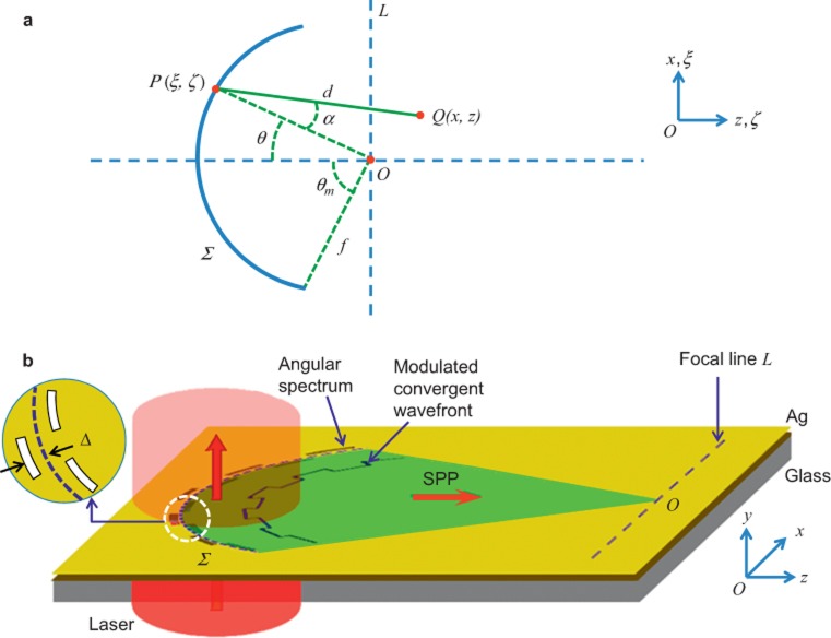
Figure 1.
(a) Schematics of in-plane FT performed by surface wave propagation. In a plane, the disturbance at any point Q(x,z) in the vicinity of focus O(0,0) can be calculated by summing up the contributions from all the points, e.g., P(ξ,ζ) on a convergent wavefront (depicted as the arc Σ with the radius f). d is the distance between P and Q. α measures the inclination angle of the distance with respect to the normal of the arc. The focal line L is perpendicular to the horizontal axis (z or ζ) across the focus. θ is the polar angle in the corresponding polar coordinates. (b) Slits in the angular spectrum represented by a reference arc are perforated in the optically opaque metal film (e.g., Ag) on a glass substrate. When illuminated by a coherent light source such as a laser, the slits generate converging SPPs at the air–Ag interface. The converging wavefront is modulated by the displacement Δ(θ) of the slits from the reference arc (blue dashed curve).

