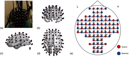
Fig. 1.
(a) A photo of the optode placement through a cap on a participant’s head. The optodes of 40 sources (red in the online version) and 40 detectors (blue in the online version) are marked and shown in (b) front view, (c) left-side view, and (d) top view. The location/place between each source–detector pair corresponds to a respective channel from 1 to 133, as labeled in (e). The (e) schematic illustration of the fNIRS 40-source and 40-detector opotodes, which were coregistrated and projected on a human brain template derived from the ICBM152 MNI space (see Sec. 2.2 for details).

