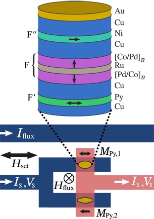
Fig. 1. Spin-triplet Josephson junction structure and SQUID loop design.

Top: Schematic cross section of the central layers in our Josephson junctions (not to scale). The central F layer is composed of two [Pd (0.9 nm)/Co (0.3 nm)]n multilayers with perpendicular magnetic anisotropy (PMA), separated by a Ru (0.95 nm) spacer to form a synthetic antiferromagnet (SAF). The outer F′ and F″ layers have in-plane magnetization; we used Permalloy (Py) for F′ and Ni for F″. One junction has an elliptical cross section (aspect ratio, 2.0) to make its F′ layer switch at a low field, while the other is an elongated hexagon (aspect ratio 3.0); both have an area of 0.5 μm2. Bottom: The two junctions are arranged into a SQUID loop. An external field Hset is used to control the magnetization directions of the F′ and F″ layers inside the junctions; all measurements are performed with Hset = 0. The current Iflux passing through a nearby superconducting line creates an out-of-plane field Hflux, which couples magnetic flux Φ into the SQUID loop. The Py magnetizations are shown as black arrows labeled MPy,1 and MPy,2.
