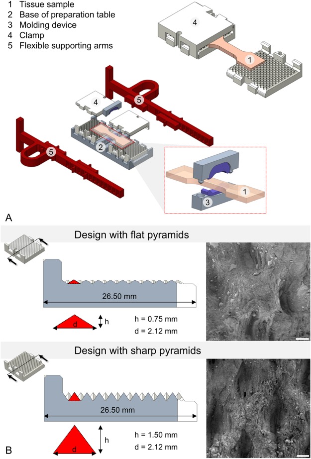
Figure 2.
(A) Mounted sample in the self-locking clamps (top right), and schematic representation of the preparation table (center of image) including a (enlarged) molding tool for the determination of cross sections of the samples prior to testing (right bottom). (B) Clamp designs with 4-sided pyramid structures in cross-sectional view. Pyramid dimensions (d = diagonal, h = height) are enlarged. Additionally, corresponding scanning electron microscopy images of clamped ligament tissues after testing at 25x magnification are represented at the right. Note the elongated impressions in the ligament tissues clamped with the sharp pyramids (scale bar 100 μm).

