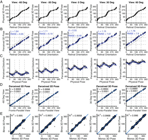
Fig. 2.
Perceived 3D poses from retinal projections. Perceived poses of sticks. Columns represent different observer viewpoints. (A) The back-projection from the 2D retinal orientation of each stick to the true 3D physical pose on the ground plane. Curves show the continuous back-projection function. (B) Perceived 3D pose against retinal orientation, averaged across eight observers. Each observer made seven judgments for each physical pose, represented by different symbols (o, single stick; x, each of acute angle paired sticks; ∆, each of right angle paired sticks; ◊ , each of obtuse angle paired sticks), binocularly and monocularly. Curves represent the best-fitting model based on the back-projection. The fronto-parallel bias as estimated from the fronto-parallel viewing condition (View 0 Deg column) is reported as K. The multiplying parameter on the camera elevation at each viewpoint is reported as L. The RMSE is given for each viewing condition. (C) Perceived distortion (perceived pose minus physical pose) is plotted against the physical 3D pose. Curves represent the distortion predicted from the best fit of the model shown above. (D) Perceived 3D pose at each viewing angle is plotted versus perceived 3D pose from the fronto-parallel viewing condition. The blue line is the line of unit slope shifted so that the y intercept is equal to the viewing angle. The correlation is reported as r. (E) Binocular 3D pose percept plotted against monocular 3D pose percept. Blue line is the line of unity. Fit of the line of unity is shown as R2.

