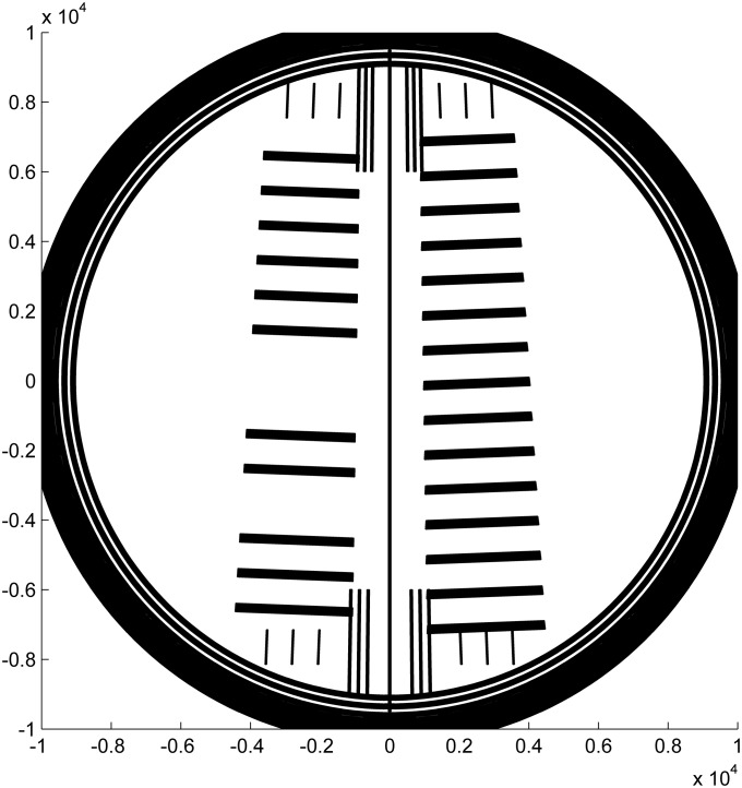
Fig 1. Drawing of the mask design.
Two scales (series of lines) are perpendicular to the radius from the center of rotation once placed in the rotor hole of the analytical ultracentrifuge. The sample side (right) and reference side (left) have the same pitch of 1 mm, but are shifted by half the pitch. A long central line and 12 short lines near the center are added as a visual guide for mounting the window into the cell assembly, to facilitate angular alignment relative to the middle divider of a centerpiece. Three short lines above and below each scale are features recognized when calibrating the artifacts for certification and encompass the angular range over which the scale pitch is determined. The units of the axis drawn are micrometers.

