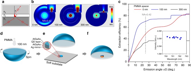
Fig. 1.
Dielectric antenna design and numerical results. a Illustration of light propagating at the media interfaces. The three media fulfill as in our design. The evanescent wave caused by total internal reflection at the interface will be coupled to the propagating wave when the intermediate gap decreases. b Far field view and cross section (inset) of dielectric antennas’ emission. PMMA spacers with different thicknesses, thus different coupling strength, are considered. The collection angle of a NA = 0.42 lens is indicated by the dashed circle. Antenna with 100 nm PMMA spacer gives the best result in terms of coupling strength and emission angle. c–e Fabrication flow of the device. The dielectric antenna consists of an AlGaAs membrane (with embedded QDs), a low refractive index PMMA spacer and the GaP solid immersion lens (SIL), with the refractive indices of n1, n2, and n3, respectively. A bottom silver mirror is used to reflect downward-emitted photons. f Numerical results for the dielectric antenna as a function of emission angle α. The collection angle of a NA = 0.42 lens is indicated by the dashed line. Inset shows the broadband operation of the dielectric antenna. All QDs randomly chosen across the membrane are bright

