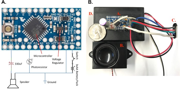
Fig 1. Diagram of sound lure.
(A) Detailed schematic of the Arduino-based sound lure (Pro Mini 3.3 V board). The lure is programmed to produce a pulse-width-modulated 484 Hz sinusoidal-approximating signal through pin 11, from which it would travel through a DC-blocking capacitor to a speaker. The device is powered via a battery pack (SBH331AS, Memory Protection Devices Inc, Farmingdale, NY), containing three AA batteries and an on/off switch. (B) Assembled sound lure with a United States quarter dollar (diameter 2.54 cm) on top of battery box for size comparison. The components are: (A) assembled Arduino board, (B) speaker, (C) wired TTL serial adapter to connect to FTDI USB to TTL serial adapter to enable programming of board (Note: this component can be removed after programming if desired) and (D) battery pack.

