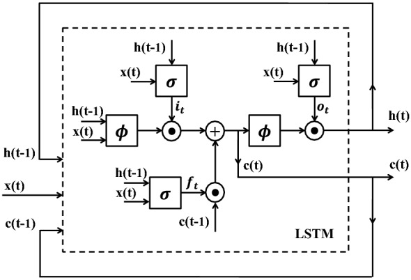
Fig. 4.

The structure of an LSTM. The system at each time-point is updated based on the current input data, the status of the system at the previous time-point, and the content of the memory. Here, and are hyperbolic tangent and sigmoid functions, respectively, and stands for the element-wise multiplication. , , and denote input gate, forget gate, output gate and memory cell respectively
